Advanced Strategies in Extrusion Die Geometry: Optimizing Flow Dynamics for Defect-Free Pharmaceutical Products
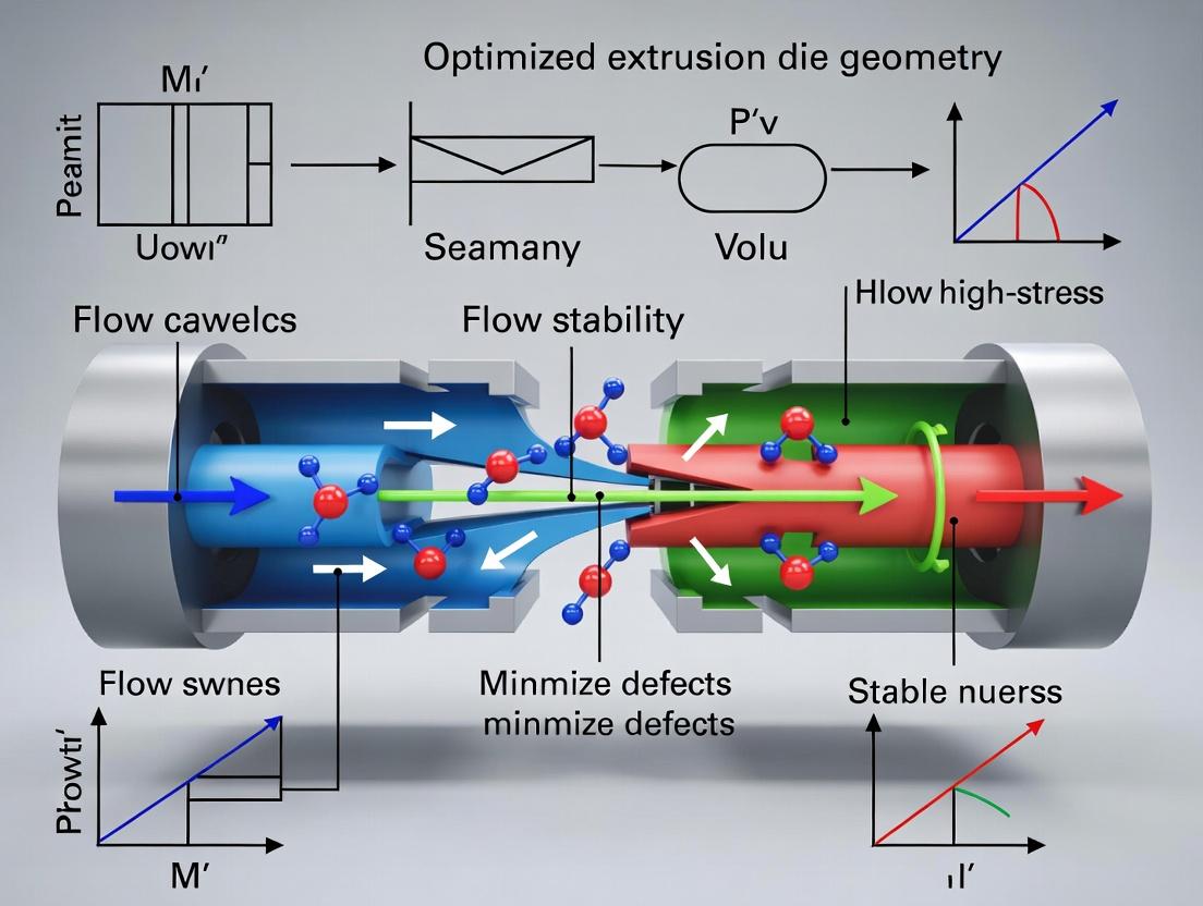
This article provides a comprehensive analysis of extrusion die geometry optimization for pharmaceutical manufacturing, targeting researchers and drug development professionals.
Advanced Strategies in Extrusion Die Geometry: Optimizing Flow Dynamics for Defect-Free Pharmaceutical Products
Abstract
This article provides a comprehensive analysis of extrusion die geometry optimization for pharmaceutical manufacturing, targeting researchers and drug development professionals. It explores the foundational fluid dynamics behind flow instability, details methodological approaches for die design and computational simulation, presents targeted troubleshooting for common defects like sharkskin and melt fracture, and validates optimization strategies through comparative case studies. The scope bridges fundamental theory with practical application to enhance product quality and manufacturing efficiency in solid dosage form and implant development.
Understanding Flow Instability: The Fluid Dynamics Behind Extrusion Defects in Pharma
The Critical Link Between Die Geometry and Product Quality in Drug Delivery Systems
Technical Support Center: Troubleshooting Hot Melt Extrusion (HME) for Drug Delivery
Frequently Asked Questions (FAQs)
Q1: During extrusion of an amorphous solid dispersion, we observe a rough, shark-skin-like surface on the extrudate. What die-related factors could be causing this, and how can we mitigate it? A: Shark-skinning is a flow instability often initiated at the die exit. It is critically linked to die geometry and processing conditions.
- Primary Cause: Excessive wall shear stress at the die land region. A short die land length or a sudden contraction ratio can amplify this.
- Solutions:
- Increase Die Land Length (L/D ratio): This allows for stress relaxation before the polymer melt exits. Aim for an L/D ratio > 10 for many pharmaceutical polymers.
- Utilize a Tapered Die Inlet: A conical (tapered) entrance (e.g., 30-45° angle) reduces elongational stress and promotes streamlined flow.
- Optimize Processing Temperature: A moderate increase in die zone temperature can reduce melt viscosity and shear stress.
- Thesis Context: This instability directly relates to optimizing die entry angle and land length to minimize exit pressure gradients and wall slip.
Q2: Our extrudate exhibits periodic gross distortions, known as melt fracture. How does die geometry contribute, and what are the corrective actions? A: Melt fracture is a severe instability occurring at higher shear stresses than shark-skin.
- Primary Cause: Excessive shear or elongational stress in the die entrance region. A sharp, abrupt contraction (e.g., a 90° entry) is a common culprit.
- Solutions:
- Implement a Streamlined Entry: Redesign the die with a hyperbolic or multi-angle tapered entry to smoothly accelerate the melt.
- Review Contraction Ratio: The ratio of barrel cross-sectional area to die orifice area. A very high ratio increases elongational stress. Consider a staged reduction.
- Polish Die Interior: A mirror-finish on the die flow channel walls reduces frictional resistance.
- Thesis Context: This underscores the thesis core: die entrance geometry must be optimized to manage elongational flow and prevent cohesive melt failure.
Q3: We are experiencing drug degradation or inconsistent API dispersion in the final filament. Could die design be a factor? A: Yes, indirectly. Poor die design leading to instabilities or uneven flow can cause excessive mechanical energy input (high shear) or non-uniform residence time.
- Primary Cause: "Dead zones" or recirculation areas in poorly designed die corners, or excessive shear heating in a long, restrictive die land.
- Solutions:
- Eliminate Stagnation Points: Design the flow path with smooth, radiused corners to ensure uniform, streamlined flow for all fluid elements.
- Balance L/D Ratio: While a long land stabilizes flow, it must be balanced against increased shear history. Computational Fluid Dynamics (CFD) simulation can help find the optimum.
- Verify Temperature Uniformity: Ensure die heaters are calibrated and the die block is properly insulated to prevent hot/cold spots.
- Thesis Context: Achieving a spatially and temporally uniform flow field via geometry optimization is key to consistent product quality and stability.
Experimental Troubleshooting Guide
Issue: Diagnosing and Quantifying Flow Instability Severity
Objective: To systematically correlate specific die geometries with observed extrudate defects and measure key processing parameters.
Protocol 1: Characterization of Instability Onset
- Materials: Twin-screw extruder, interchangeable dies (varying L/D ratios: 5, 10, 20; and entry angles: 45°, 90°, streamlined), polymer carrier (e.g., HPMCAS, PVPVA), API, data logger.
- Method: a. Process a standard formulation at a constant screw speed and temperature profile. b. For each die, incrementally increase the screw speed (RPM) while monitoring die pressure (via transducer) and motor torque. c. Visually inspect and capture macro-images of the extrudate at each speed interval. d. Record the critical screw speed (and calculated wall shear stress) at which shark-skin or melt fracture first appears.
- Data Analysis: Plot wall shear stress at instability onset vs. die L/D ratio. Correlate specific defect types with entry angle.
Protocol 2: Assessing API Distribution Uniformity
- Materials: As above, a well-mixed formulation with a fluorescent tracer or API with distinct UV signature, microtome, UV-microscope or NIR chemical imaging.
- Method: a. Extrude using a die suspected to have poor flow dynamics (e.g., 90° entry) and an optimized die (streamlined entry). b. Collect and quench-cool extrudate strands from each run. c. Cross-section the strands using a microtome to expose the interior. d. Analyze the cross-sections using chemical imaging to map API/tracer distribution.
- Data Analysis: Calculate the Relative Standard Deviation (RSD) of API signal intensity across the cross-section for each die. Lower RSD indicates more uniform distribution.
Data Presentation
Table 1: Impact of Die Land Length (L/D) on Instability Onset and Product Properties
| Die Land L/D Ratio | Critical Shear Stress for Shark-skin (kPa) | Extrudate Diameter Consistency (RSD%) | API Content Uniformity (RSD%) |
|---|---|---|---|
| 5 | 150 | 3.5 | 12.4 |
| 10 | 220 | 1.2 | 5.2 |
| 20 | 250 | 1.0 | 4.8 |
Table 2: Effect of Die Entry Angle on Observed Defects and Process Parameters
| Die Entry Geometry | Primary Defect Observed | Pressure Drop (MPa) @ 100 rpm | Maximum Stable Screw Speed (rpm) |
|---|---|---|---|
| 90° (Abrupt) | Severe Melt Fracture | 12.5 | 75 |
| 45° (Tapered) | Mild Shark-skin | 10.2 | 125 |
| Streamlined (Hyperbolic) | Smooth Surface | 9.8 | 150 |
Visualizations
Title: Die Geometry's Role in Product Quality
Title: Die-Related Defect Troubleshooting Flowchart
The Scientist's Toolkit: Research Reagent Solutions
| Item/Category | Function in Die Geometry Research | Example Product/Specification |
|---|---|---|
| Modular Capillary Dies | Enable systematic study of L/D ratio and entry angle effects. Interchangeable parts for a single extruder. | Custom-machined dies (e.g., 2mm diameter, L/D: 5-30, entry angles: 15°-180°). |
| Pressure Transducers | Measure pressure drop across the die, essential for calculating wall shear stress and detecting instabilities. | Melt pressure sensor, rated for >50 MPa, temperature stable up to 300°C. |
| Data Acquisition System | Logs pressure, temperature, torque, and screw speed in real-time for correlating process signals with defects. | LabVIEW or similar system with ≥10 Hz sampling rate. |
| High-Speed Camera | Captures the onset and evolution of surface defects at the die exit. | Camera with ≥1000 fps and macro lens. |
| Rheological Additives | Fluorescent tracers or model APIs used to visualize mixing and distribution within the extrudate. | <1% w/w Rhodamine B or quinine sulfate for UV/fluorescence imaging. |
| Computational Fluid Dynamics (CFD) Software | Simulates velocity profiles, shear rates, and stress fields inside proposed die geometries before fabrication. | ANSYS Polyflow, COMSOL Multiphysics with polymer flow module. |
| Microtome | Prepares clean, thin cross-sections of extrudate for microscopic analysis of internal structure and API distribution. | Laboratory rotary microtome with carbide blades. |
| Chemical Imaging System | Maps the spatial distribution of components (e.g., API, polymer) across an extrudate cross-section. | NIR or Raman chemical imaging microscope. |
Technical Support Center: Troubleshooting and FAQs
This support center is designed for researchers in the context of thesis work focused on Optimizing extrusion die geometry to minimize flow instability and defects. The following guides address specific, experimentally observed phenomena.
FAQ 1: During my capillary rheometer experiment with a polymer-drug blend, I observe a fine, matte, periodic roughness on the extrudate surface. It looks like the skin of a shark. What is this, and what are the primary geometric and operational factors?
Answer: You are observing Sharkskin (Surface Melt Fracture). It is a surface instability initiating at the die exit due to rapid acceleration and tensile stress as the polymer melt detaches from the die wall. It is highly dependent on exit geometry and wall shear stress.
- Key Factors:
- Die Geometry: A sharp, 90-degree die exit angle promotes sharkskin. A tapered or rounded exit (radiussed die land) allows for a more gradual velocity profile transition, reducing the defect.
- Operational Parameters: Onset is primarily a function of wall shear stress (typically > 0.1 MPa for many polymers) and temperature. Lower temperatures exacerbate it.
Experimental Protocol for Onset Characterization:
- Material: Condition your polymer/API blend at a standard moisture content.
- Tool: Use a capillary rheometer with a series of dies of identical diameter but different land lengths (e.g., L/D = 5, 10, 20) and an option for a radiussed exit.
- Method: Conduct apparent shear rate sweeps at a constant temperature (e.g., 150°C, 170°C, 190°C).
- Measurement: For each sweep, visually (via microscope) or via laser scan identify the shear stress at which the first periodic surface roughness appears. This is the critical shear stress for sharkskin onset.
- Analysis: Use the Bagley correction to determine the true wall shear stress at onset. Correlate onset stress with die exit angle and L/D ratio.
Table 1: Typical Onset Parameters for Common Pharmaceutical Polymers (Model Values)
| Polymer/Blend | Typical Processing Temp (°C) | Critical Wall Shear Stress for Sharkskin Onset (MPa) | Mitigating Die Geometry Factor |
|---|---|---|---|
| HPMC (Hypromellose) | 160-180 | ~0.12 - 0.15 | Radiussed exit (R=0.5mm), Increased land length |
| PEO (Polyethylene Oxide) | 80-100 | ~0.08 - 0.12 | Tapered entrance (180° included angle), Smooth bore finish |
| Eudragit E PO | 130-150 | ~0.15 - 0.20 | Increased die temperature (>10°C above barrel) |
| PLGA | 80-120 | ~0.25 - 0.35 | Larger die diameter (reduces shear rate) |
FAQ 2: At higher rates, my extrudate becomes severely distorted—showing helical, bamboo, or chaotic breaks. This occurs after sharkskin. What is happening, and how is it related to die design?
Answer: This is Gross Melt Fracture. It originates within the die, typically at the entrance contraction zone, due to elastic instabilities and unbalanced flow. It is a more severe defect than sharkskin and is strongly influenced by entrance geometry and reservoir design.
- Key Factors:
- Die Geometry: A sudden, abrupt contraction (e.g., from a large barrel to a small die) creates vortex-like recirculation (stagnation zones) called "entrance vortices." Unstable elastic energy release from these vortices causes gross fracture.
- Operational Parameters: Onset is a function of a critical recoverable shear strain or Weissenberg number, linking elasticity, shear rate, and die geometry.
Experimental Protocol for Mapping the Instability Envelope:
- Material: Use the same conditioned blend.
- Tool: Capillary rheometer with a Bagley correction design (orifice dies).
- Method: Perform shear rate sweeps using dies with the same diameter but different entrance angles (e.g., 180° flat, 120°, 60°, 30° tapered).
- Measurement: Record the pressure trace and visually capture extrudate. The onset of pressure oscillations and severe distortion marks gross melt fracture.
- Analysis: Calculate the entry pressure drop (via Bagley plot) and the extensional stress at the contraction for each geometry. Plot onset shear rate vs. entrance angle.
Diagram 1: Flow Instability Pathways in Capillary Die
FAQ 3: My extrudate diameter is larger than the die diameter, affecting my final dosage form dimensions. What is this "swell," and how do I quantify and control it through die design?
Answer: This is Die Swell (Extrudate Swell). It is a manifestation of polymer melt elasticity. Upon exiting the confinement of the die, the stored elastic energy (from shear and extensional deformation within the die) is recovered, causing the polymer to expand. It is directly linked to first normal stress differences and die residence time.
- Key Factors:
- Die Geometry: Land length (L/D) is the most critical factor. A longer land allows for more stress relaxation via viscous flow, reducing swell. Swell Ratio (B = Dextrudate / Ddie) decreases asymptotically with increasing L/D.
- Operational Parameters: Swell increases with increasing shear rate (more elastic energy) and decreases with increasing temperature (enhanced relaxation).
Experimental Protocol for Measuring Swell Ratio vs. L/D:
- Material: Conditioned polymer/API blend.
- Tool: Capillary rheometer with a set of dies of the same diameter but varying land lengths (e.g., L/D = 0 (orifice), 5, 10, 20, 30).
- Method: Extrude at a constant, representative shear rate (e.g., 100 s⁻¹) and temperature. Allow extrudate to cool without tension.
- Measurement: Using a laser micrometer or calibrated microscope, measure the diameter of the cooled, stable extrudate at multiple points. Calculate the average swell ratio B.
- Analysis: Plot B vs. L/D. Fit a decaying exponential model: B = B∞ + (B0 - B∞) * exp(-k * L/D), where B∞ is the asymptotic swell at infinite land length.
Table 2: Die Swell Ratio (B) Dependency on Die Land Length (L/D) for a Model Polymer at Constant Shear Rate
| Die Land Length-to-Diameter Ratio (L/D) | Measured Swell Ratio (B) | Extrudate Diameter (mm) from 1mm Die | Key Implication for Die Design |
|---|---|---|---|
| 0 (Orifice) | 1.80 | 1.80 | Maximum swell, worst for dimensional control. |
| 5 | 1.50 | 1.50 | Significant swell; requires post-process calibration. |
| 10 | 1.35 | 1.35 | Common starting point for design. |
| 20 | 1.22 | 1.22 | Good for dimensional accuracy; higher pressure needed. |
| 30 | 1.18 | 1.18 | Near-asymptotic value; optimal for precision. |
The Scientist's Toolkit: Key Research Reagent Solutions
| Item | Function in Extrusion Defect Research |
|---|---|
| Capillary Rheometer | Primary instrument for applying controlled shear/pressure and measuring viscosity, pressure drop, and extrudate appearance. |
| Tungsten Carbide Capillary Dies | High-precision, wear-resistant dies with defined L/D ratios, entrance angles, and exit radii for geometric studies. |
| Laser Micrometer / High-Speed Camera | For non-contact, precise measurement of extrudate diameter (swell) and real-time visualization of instability onset. |
| Bagley Correction Dies (Orifice Dies) | Zero-length or very short dies used to separate entrance pressure loss from land pressure loss, critical for true shear stress calculation. |
| Rheological Additives (e.g., Fluoropolymer Process Aids) | Used as processing aids in trace amounts (<0.1%) to study their effect on delaying sharkskin and melt fracture via wall slip. |
| Thermal Imaging Camera | To monitor die exit temperature gradients, which can influence sharkskin and swell. |
| Model Polymer (e.g., HDPE, PS) | Well-characterized, defect-prone polymers used for initial method development and fundamental instability studies before testing API blends. |
Technical Support Center
Troubleshooting Guides & FAQs
Q1: During capillary rheometry of a hot-melt extruded API-polymer blend, we observe significant pressure oscillations and erratic extrusion rates. What is the primary cause and how can we mitigate it?
A: This is a classic symptom of flow instability, often "melt fracture," driven by viscoelasticity. When the elastic stresses (normal stress differences) exceed a critical value at the die entrance or wall, the flow becomes unstable.
- Primary Cause: Excessive shear stress or extensional stress at the die entrance, combined with high material elasticity (relaxation time).
- Mitigation Protocol:
- Increase Die Land Length (L/D ratio): A longer land reduces elastic recoil and promotes stress relaxation. For preliminary trials, increase L/D from 10 to 20.
- Increase Processing Temperature: Lower viscosity and shorter relaxation time reduce elastic energy storage. Increase in 5-10°C increments, monitoring API stability.
- Incorporate a Processing Aid/Plasticizer: Adding 0.5-2% w/w of a compatible plasticizer (e.g., triethyl citrate, PEG) can significantly reduce melt elasticity.
- Modify Die Entry Angle: Implement a tapered (converging) die entry with an angle of 30-45° to reduce extensional stress concentrations.
Q2: Our extrudate for an amorphous solid dispersion exhibits severe sharkskin (surface mattiness/ridging) at high throughput, even with smooth die walls. How do we diagnose and address this?
A: Sharkskin is a surface instability originating at the die exit due to rapid elastic recovery of the polymer.
- Diagnosis: Perform flow curve analysis. Sharkskin typically initiates at a critical wall shear stress, often between 0.1-0.4 MPa for many pharmaceutical polymers.
- Experimental Protocol to Identify Critical Point:
- Using a capillary rheometer with a 1mm diameter, 16:1 L/D round die, conduct steady-state shear sweeps.
- Measure apparent shear stress (∆P*R/2L) and visually/microscopically inspect extrudates at each shear rate.
- Plot shear stress vs. shear rate and note the stress value where surface defects first appear.
- Solutions:
- Optimize Die Geometry: Implement a dual-land die or a die with a small, controlled vacuum at the exit to mitigate stress snapping.
- Blend Polymers: Blend a low molecular weight fraction (e.g., 10-20% of a similar polymer with lower Tg) to facilitate surface healing.
- Post-Die Calibration: A short, heated post-die sleeve can allow surface relaxation before the extrudate fully solidifies.
Q3: How do we quantitatively measure the viscoelastic properties of a novel API-polymer blend to inform die design?
A: Small-Amplitude Oscillatory Shear (SAOS) is the key technique.
- Experimental Protocol:
- Sample Prep: Compress molded disks of the HME blend (post-extrusion) to ensure homogeneity.
- Frequency Sweep Test: On a parallel-plate rheometer (e.g., 8mm diameter, 1mm gap), at a fixed temperature (e.g., processing T), perform a frequency sweep from 100 to 0.1 rad/s at a strain within the linear viscoelastic region (determined by prior amplitude sweep).
- Key Data: Record storage modulus (G'), loss modulus (G''), complex viscosity (η*), and tan δ (G''/G').
- Analysis: The crossover point (G' = G'') indicates the transition from elastic- to viscous-dominated behavior. The relaxation spectrum, derived from G' and G'' data, is critical for die flow modeling.
Table 1: Critical Shear Stresses for Flow Instabilities in Common Pharmaceutical Polymers
| Polymer/Blend (Typical 20% API Load) | Processing Temp (°C) | Sharkskin Onset Shear Stress (kPa) | Gross Melt Fracture Shear Stress (kPa) |
|---|---|---|---|
| PVP-VA (Kollidon VA64) | 150 | ~120 | ~350 |
| HPMC-AS (AQOAT) | 170 | ~90 | ~280 |
| Soluplus | 130 | ~150 | ~400 |
| Eudragit E PO | 140 | ~110 | ~330 |
Table 2: Effect of Die Geometry on Extrudate Defects in Model API-Polymer System
| Die Geometry (Entry Angle / L/D) | Wall Shear Rate (1/s) | Observed Defect | Pressure Drop (MPa) | Normal Stress Difference (N1) Estimate (kPa) |
|---|---|---|---|---|
| Flat / 10:1 | 100 | Severe Sharkskin | 4.2 | 85 |
| 45° Taper / 10:1 | 100 | Mild Sharkskin | 3.8 | 72 |
| 30° Taper / 20:1 | 100 | Smooth | 5.1 | 65 |
| 30° Taper / 20:1 | 300 | Onset of Matte Surface | 12.5 | 210 |
Experimental Protocols
Protocol: Determining Linear Viscoelastic Region (LVR)
- Equipment: Rotational rheometer with parallel-plate geometry.
- Method: At a fixed frequency (e.g., 10 rad/s) and processing temperature, perform a strain (or stress) amplitude sweep from 0.01% to 100%.
- Analysis: Plot G' and G'' versus % strain. Identify the maximum strain (%) where G' remains constant. This defines the upper limit of the LVR for subsequent frequency sweeps.
Protocol: Capillary Rheometry for Flow Curve & Instability Mapping
- Equipment: Dual-bore capillary rheometer equipped with round dies of varying L/D.
- Method:
- Load pre-dried, granulated blend. Allow thermal equilibration for 5 minutes.
- Perform a series of constant piston speed tests to cover shear rates from 1 to 1000 1/s.
- At each speed, record steady-state pressure and collect extrudate samples.
- Perform Bagley (pressure drop vs. L/D) and Rabinowitsch (non-parabolic flow profile) corrections.
- Analysis: Generate true viscosity vs. shear rate curves. Correlate specific defects (sharkskin, stick-slip, gross fracture) with critical corrected shear stress values.
The Scientist's Toolkit: Research Reagent Solutions
Table 3: Essential Materials for Rheology-Driven Extrusion Optimization
| Item | Function & Rationale |
|---|---|
| Parallel-Plate Rheometer (e.g., 8-25mm diameter plates) | For SAOS testing to characterize linear viscoelastic properties (G', G'', η*, relaxation time) crucial for die flow simulations. |
| Capillary Rheometer with Bagley & Rabinowitsch Correction Capability | For measuring high-shear viscosity and directly observing processing defects under relevant conditions. |
| Modular Extrusion Die Kit (Interchangeable inserts for land length, entry angle) | For systematic experimental study of geometry effects on flow stability and extrudate quality. |
| Laser Scanning Confocal Microscope or High-Resolution SEM | For quantitative 3D surface analysis of extrudate defects (sharkskin depth, periodicity). |
| Processing Aids/Plasticizers (Triethyl Citrate, PEG 400-6000, Tween 80) | To modify viscoelastic balance, reduce elasticity, and shift the critical shear stress for instabilities. |
Diagrams
Diagram 1: Viscoelasticity-Driven Instability Mechanism
Diagram 2: Experimental Workflow for Die Geometry Optimization
Troubleshooting Guide & FAQs
Q1: During polymer extrusion, we observe significant surface defects (shark skin) at high rates. We suspect wall shear stress (τ_w) is too high. How can we diagnose and mitigate this? A: Excessive wall shear stress is a primary driver for flow instabilities like sharkskin. To diagnose:
- Calculate τw: Use the Weissenberg-Rabinowitsch correction for non-Newtonian fluids in your die land. τw = (ΔP * R) / (2 * L), where ΔP is the pressure drop over a capillary of radius R and length L. For a power-law fluid, τ_w = K * ( (3n+1)/4n * (8V/D) )^n, where K is consistency index, n is power-law index, V is average velocity, and D is diameter.
- Compare to Critical Threshold: Literature suggests sharkskin onset often occurs at a critical τ_w between 0.1-0.4 MPa for many polymers (e.g., ~0.14 MPa for HDPE).
- Mitigation Strategies: To reduce τ_w and delay instability:
- Increase die land temperature to reduce melt viscosity.
- Incorporate a processing aid (e.g., fluoropolymer) to promote wall slip.
- Optimize die geometry: Increase the die land radius or decrease the land length (L) to reduce ΔP, or implement a more gradual entrance angle.
Q2: Our pressure drop (ΔP) measurements in a tapered entry die are consistently higher than theoretical predictions. Could the die entrance angle be the cause? A: Yes. A sharp entrance angle (e.g., 90°) causes a significant vortex and elongational flow, leading to excess pressure loss not captured by simple shear-flow models. This is the entrance pressure loss (ΔP_ent).
- Diagnosis: Measure ΔP at varying flow rates for dies with identical land dimensions but different entrance angles (e.g., 15°, 30°, 45°, 90°). Plot Bagley-corrected pressure vs. angle.
- Protocol: Perform a Bagley correction to separate total ΔP into entrance and land contributions. Use two dies with the same radius but different land lengths (L1, L2).
- Measure total pressure (P1, P2) at the same shear rate.
- Plot P vs. L/R. The y-intercept is ΔPent. The slope is related to τw.
- Solution: Redesign the die with an optimal taper angle (typically 15-30°) to streamline flow, minimize vortices, and reduce ΔP_ent.
Q3: When extruding a sensitive bio-polymer for drug delivery, we see inhomogeneous mixing and degradation. How do entrance effects relate to this? A: A poorly designed entrance can create stagnation zones (dead spaces) where material resides for extended periods, leading to thermal degradation. It also generates high, heterogeneous elongational stresses that can denature shear-sensitive bio-polymers.
- Action: Implement a streamlined, conical entrance (≤ 30°). Consider a rounded ( trumpet-shaped ) entry to eliminate sharp corners entirely.
- Material Consideration: For thermolabile compounds, use dies with low-surface-energy coatings (e.g., chromium, Teflon-like) to reduce wall adhesion and slip-stick instability.
Table 1: Critical Wall Shear Stress for Onset of Flow Instabilities in Common Polymers
| Polymer Type | Critical τ_w for Sharkskin (MPa) | Critical τ_w for Stick-Slip (MPa) | Test Conditions (Approx.) |
|---|---|---|---|
| HDPE | 0.12 - 0.15 | 0.25 - 0.30 | 180°C, Capillary Die |
| LDPE | 0.10 - 0.18 | Not typically observed | 160°C |
| PP | 0.08 - 0.12 | 0.15 - 0.20 | 200°C |
| PS | 0.08 - 0.10 | 0.10 - 0.15 | 200°C |
| PDMS (Silicone) | 0.04 - 0.06 | - | 25°C |
Table 2: Effect of Die Entrance Angle on Pressure Drop and Vortex Size
| Entrance Angle (Degrees) | Normalized Entrance Pressure Drop (ΔPent/τw) | Vortex Intensity & Stagnation | Recommended Use Case |
|---|---|---|---|
| 15° - 30° | 1.0 - 1.5 | Minimal / None | Optimal for sensitive, viscous melts |
| 45° | 1.8 - 2.2 | Moderate | General purpose extrusion |
| 90° (Flat) | 3.0 - 4.0+ | Severe, Large Stagnation Zone | Avoid for unstable or sensitive materials |
Experimental Protocols
Protocol 1: Determining Critical Wall Shear Stress for Instability Onset Objective: Identify the wall shear stress at which sharkskin or stick-slip defects begin. Materials: Capillary rheometer, dies with L/D=20 and L/D=5 (same diameter), polymer sample. Method:
- Preheat rheometer and dies to target processing temperature. Equilibrate sample.
- For a series of controlled piston speeds (flow rates), measure the steady-state pressure (P) using the long die (L/D=20).
- Repeat with the short die (L/D=5).
- For each shear rate, plot the measured pressure against the die land length (L). Perform a linear fit (Bagley plot).
- The y-intercept gives the total end correction (entrance+exit pressure loss). The slope gives 2τ_w/R.
- Extrude strands at each shear rate and visually (or via microscopy) inspect for surface defects.
- Correlate the calculated τw from step 5 with the observed defect onset to determine the critical τw.
Protocol 2: Characterizing Entrance Angle Effects via Flow Visualization Objective: Qualitatively and quantitatively assess vortex formation. Materials: Transparent slit die with interchangeable entrance inserts (15°, 45°, 90°), tracer particles, high-speed camera, pump for Newtonian or well-characterized fluid (e.g., silicone oil). Method:
- Fill the reservoir with the test fluid seeded with tracer particles.
- Set the pump to a constant volumetric flow rate.
- For each entrance insert, record high-speed video of the flow in the entrance region.
- Use Particle Image Velocimetry (PIV) software or manual tracking to calculate velocity fields and identify stagnation zones/vortex boundaries.
- Simultaneously, record the pressure transducer reading upstream of the entrance.
- Compare the measured ΔP and visualized flow patterns across the different angles.
Visualizations
Troubleshooting Flow for Extrusion Instabilities
Pressure Drop Components in an Extrusion Die
The Scientist's Toolkit: Research Reagent & Material Solutions
Table 3: Essential Materials for Extrusion Die Flow Studies
| Item | Function & Rationale |
|---|---|
| Capillary Rheometer | Provides controlled shear/pressure-driven flow. Essential for measuring viscosity, τ_w, and ΔP under processing conditions. |
| Modular Die Inserts | Interchangeable capillaries/slits with varying L/D ratios and entrance angles. Critical for Bagley corrections and geometry studies. |
| Pressure Transducers (Flush Diaphragm) | Accurately measure pressure at die inlet and along land. Must be flush-mounted to avoid dead volume. |
| High-Temperature, High-Speed Camera | For flow visualization and direct observation of instability onset in transparent dies. |
| Optical Microscope / Profilometer | Quantitative analysis of extrudate surface roughness and defect characterization. |
| Processing Aids (e.g., Fluoropolymer Elastomers) | Additives that migrate to die wall to induce slip, reducing τ_w and delaying sharkskin. |
| Stable, Well-Characterized Test Polymers (e.g., HDPE, PDMS) | Reference materials with known rheology and critical stresses for validating experimental setups. |
| Tracer Particles (e.g., Glass Beads, Mica) | For flow visualization and Particle Image Velocimetry (PIV) in model fluids to map streamlines and vortices. |
| Non-Stick Coatings (Chromium, PVD Coatings) | Applied to die surfaces to reduce adhesion and wall shear stress for challenging materials. |
Technical Support Center: Troubleshooting Polymer Extrusion Instabilities
FAQ 1: How do I distinguish between melt fracture and sharkskin in my extruded biopolymer filament?
- Answer: Both are surface defects but differ in appearance and root cause. Sharkskin presents as a regular, high-frequency, ridge-like pattern perpendicular to the flow direction. Melt fracture is a more severe, gross distortion with a chaotic, wavy, or helical pattern. Sharkskin is often linked to high shear stress at the die exit, while melt fracture is associated with cohesive failure within the die land due to excessive shear or tensile stress. For diagnostics, systematically reduce the extrusion rate; sharkskin may disappear at a critical lower shear rate, while melt fracture will persist until a much lower rate is reached.
FAQ 2: Why does my drug-loaded PLLA filament exhibit periodic "puffing" or bubbling after extrusion?
- Answer: This is likely a volumetric instability driven by moisture-induced degradation. Bio-polymers like PLLA and PLGA are hygroscopic. Ingressed water acts as a plasticizer and, at extrusion temperatures, can cause hydrolytic scission of polymer chains, leading to a rapid drop in viscosity and the formation of volatile oligomers. This creates a stick-slip flow instability and bubble formation. Ensure all raw materials are dried in a vacuum oven (<100 mbar) at 55°C for a minimum of 6 hours prior to extrusion. Use desiccant-filled hopper dryers during processing.
FAQ 3: What causes inconsistent polymer melt pressure and output surging during a long-duration run?
- Answer: Inconsistent pressure and surging are hallmark signs of feedstock inconsistency or thermal degradation. For bio-polymers, this can be caused by:
- Poor thermal stability: Extended residence time in the barrel leads to molecular weight reduction. Optimize temperature profile and use a shorter L/D ratio die.
- Wall slip-stick cycles: Additives or low-MW fractions can create an unstable lubricating layer at the die wall.
- Poorly controlled solid feeding (if using pellets): Ensure uniform pellet size and use a crammer feeder. Implement a Methodology for Stability Assessment: Record pressure transducer data at 10 Hz. Calculate the coefficient of variation (CV) of the pressure signal over a 5-minute window. A CV >5% indicates significant instability. Correlate pressure CV with the observed defect frequency from in-line laser micrometry.
FAQ 4: How can I experimentally determine the critical shear rate for the onset of flow instability for a new polymer blend?
- Answer: Follow this Capillary Rheometry Protocol:
- Equilibration: Load dried polymer into the rheometer barrel, compress, and equilibrate for 5 minutes at target temperature (e.g., 180°C for PLLA).
- Shear Rate Ramp: Perform a series of constant-piston-speed experiments across a range (e.g., 10 to 1000 s⁻¹). Use a capillary die with a minimum L/D of 20 to minimize entrance effects.
- Data Collection: At each speed, allow pressure to stabilize (typically 2-3 min), then record the apparent shear stress and collect the extrudate.
- Analysis: Visually inspect extrudate samples under a digital microscope. Plot apparent shear stress vs. apparent shear rate (log-log). The critical shear rate (γ̇_c) is identified at the point where the flow curve deviates from linearity (power-law) and/or where visual defects are first consistently observed.
Table 1: Quantitative Data from Recent Studies on Bio-Polymer Instability Thresholds
| Polymer System | Critical Shear Rate (s⁻¹) @ Temp | Observed Primary Instability | Key Mitigation Strategy Studied |
|---|---|---|---|
| PLGA (50:50, 0.5 dL/g) | 250 @ 80°C | Volumetric "puffing" | Addition of 5% w/w Tributyl Citrate plasticizer increased γ̇_c to 480 s⁻¹ |
| PLLA (High Mw) | 850 @ 190°C | Sharkskin | Die exit heating to 210°C eliminated sharkskin up to 1200 s⁻¹ |
| PCL / Drug Composite | 120 @ 70°C | Melt Fracture | Optimized die inlet angle from 90° to 45° reduced entrance pressure drop by 30% |
| Gelatin-HPMC Hydrogel | 15 @ 40°C | Elastic Sagging | Rheological modification with 1M NaCl increased elastic modulus (G') by 200% |
The Scientist's Toolkit: Research Reagent Solutions for Extrusion Stability
| Item | Function & Relevance to Stability |
|---|---|
| Twin-Screw Micro-compounder (e.g., Haake Minilab) | Allows precise control of shear history, temperature, and residence time for screening small batch (5-10g) formulations. |
| In-line Melt Pressure Transducer | Essential for monitoring real-time stability and identifying pressure oscillations linked to instabilities. |
| Capillary Rheometer with Bagley Correction | The gold standard for measuring true shear viscosity and establishing accurate γ̇_c without entrance effect artifacts. |
| Planar Laser Micrometer | For non-contact, real-time measurement of extrudate diameter variations, quantifying surging or draw resonance. |
| Thermal Stabilizer (e.g., Polycarbodiimide) | Reactive additive that scavenges carboxyl end-groups in polyesters, slowing molecular weight drop during processing. |
| Process Aid (e.g., Soy Lecithin, MgSt) | Can promote wall slip in a controlled manner, shifting the onset of sharkskin to higher shear rates. |
Experimental Protocol: Evaluating Die Geometry Modifications Title: Protocol for Die Land Length and Angle Optimization
- Design: Fabricate a series of capillary dies with varying land lengths (L/D: 5, 10, 20, 30) and entry angles (180° flat, 90°, 60°, 45°, 30° conical).
- Baseline Test: Using a standard die (L/D=20, 180° entry), establish the baseline pressure drop and critical shear rate for your polymer.
- Systematic Test: For each new die, repeat the shear rate ramp protocol (see FAQ 4). Record the steady-state pressure at a fixed shear rate (e.g., 100 s⁻¹).
- Analysis: Calculate the Bagley corrected pressure drop and extensional stress at the die inlet using the Cogswell model. Plot these stresses against entry angle. The optimal geometry minimizes extensional stress while maintaining sufficient land length to relax entry disturbances.
Title: Bio-Polymer Extrusion Flow Instability Decision Pathway
Title: Experimental Workflow for Instability Onset Determination
Die Design Methodologies: Computational and Experimental Approaches for Optimal Geometry
Computational Fluid Dynamics (CFD) Simulation for Die Flow Path Analysis
Troubleshooting Guides & FAQs
Q1: The CFD solver diverges immediately when simulating polymer flow through a complex die geometry. What are the primary causes and solutions?
A: Immediate divergence typically indicates fundamental setup issues.
- Cause 1: Excessively high initial/inlet velocity or pressure. The solver cannot stabilize from the extreme initial conditions.
- Solution: Start with very low inlet velocities (e.g., 0.001 m/s) and use ramping functions to gradually increase to the target flow rate over several solver iterations.
- Cause 2: Inappropriate or missing material model parameters (e.g., for non-Newtonian shear-thinning fluids).
- Solution: Verify viscosity model constants (e.g., Power Law
n,K) from rheometry data. Use a generalized Newtonian model (Carreau, Cross) if Power Law diverges at zero shear rate. Ensure consistency of units.
- Solution: Verify viscosity model constants (e.g., Power Law
- Cause 3: Poor mesh quality in critical regions (taper, corners).
- Solution: Implement local mesh refinement in areas of high expected shear. Maintain skewness < 0.85 and aspect ratio < 100 for critical cells. Use prism layers near walls.
Q2: How do I accurately model wall slip, a critical phenomenon in extrusion die flow instability?
A: Wall slip is central to defects like sharkskin. Implement a slip model at die walls.
- Method: Use a non-linear Navier slip law:
u_slip = β * τ_w^m, whereu_slipis slip velocity,τ_wis wall shear stress, andβ&mare empirical coefficients. - Protocol: Obtain
βandmfrom capillary rheometry experiments with dies of different diameters (Mooney analysis). In your CFD software, apply this as a user-defined function (UDF) for wall boundary condition. - Tip: Start with a linear slip law (
m=1) for stability before introducing non-linearity.
Q3: My simulation shows unrealistic pressure oscillations in the die land region. Is this a numerical artifact or a predicted physical instability?
A: Distinguishing between the two is crucial for thesis validation.
- Diagnosis Steps:
- Mesh Independence Check: Run simulations with 1.5x and 2x mesh density. If oscillation frequency/amplitude changes drastically, it's likely numerical.
- Temporal Discretization: Reduce time step by an order of magnitude. Persistent oscillations suggest a physical instability.
- Model Assessment: Physical instabilities (e.g., stick-slip) are often sensitive to specific wall boundary conditions and temperature-dependent viscosity. Add a transient energy equation if not included.
- Solution for Numerical Artifacts: Switch to higher-order discretization schemes (e.g., 2nd order upwind for momentum) and use pressure-velocity coupling algorithms like COUPLED or SIMPLEC.
Q4: What are the best practices for validating CFD die flow results against experimental data for thesis research?
A: A rigorous validation protocol is essential.
- Protocol: Conduct a Design of Experiments (DoE) comparing three key metrics.
- Data Table: Validation Metrics & Protocol
| Metric | Experimental Measurement Method | CFD Output | Acceptance Criterion for Thesis Validation |
|---|---|---|---|
| Total Pressure Drop (ΔP) | In-line pressure transducers at die inlet and outlet. | Volume integral of pressure over inlet/outlet surfaces. | Difference < 10% across the operational flow rate range. |
| Exit Velocity Profile | Laser Doppler Velocimetry (LDV) or Particle Image Velocimetry (PIV) at die exit. | Velocity vector field on exit plane. | Normalized root-mean-square error (NRMSE) of velocity < 15%. |
| Wall Shear Stress (τ_w) | Indirectly via ΔP in a capillary die of known L/D. |
Contour plot on die wall surface. | Trend and magnitude match rheological prediction; identify high-risk zones (> critical stress for defect onset). |
Q5: How can I efficiently simulate and optimize multiple die geometries within my thesis timeline?
A: Use parametric design and response surface methodology (RSM).
- Workflow: 1) Create a parameterized CAD model (key variables: land length
L, taper angleα, manifold radiusR). 2) Use ANSYS DesignXplorer, COMSOL Optimization Module, or open-source Dakota to automate mesh generation and simulation. 3) Define Objective Functions (minimize: pressure drop, shear stress variation; maximize: exit flow uniformity). 4) Run a set of DoE simulations (e.g., Central Composite Design) to build an RSM. 5) Use the RSM to predict the optimal geometry without simulating every possibility.
Experimental & Computational Protocols
Protocol 1: Determining Critical Wall Shear Stress for Melt Fracture Onset
- Objective: Establish the wall shear stress threshold (
τ_critical) for flow instability. - Materials: Polymer resin, capillary rheometer with interchangeable dies.
- Method:
- Perform capillary rheometry at constant temperature across a range of shear rates.
- Record pressure drop (
ΔP) and visually inspect extrudate for sharkskin or gross melt fracture. - Calculate apparent wall shear stress:
τ_w = (ΔP * R) / (2 * L). - Correlate
τ_wwith the onset of visible extrudate distortion.
- Output: A table of
τ_criticalfor your material, used to benchmark CFD warnings.
Protocol 2: CFD Simulation of a Prototype Die Geometry
- Pre-processing:
- Geometry: Clean, watertight CAD model in
.stepformat. - Meshing: Hybrid mesh (polyhedral in core, 5-10 prism layers at walls). Target
y+≈ 1 for accurate shear capture. - Physics: Transient, pressure-based solver. Fluid: non-Newtonian (Carreau model). Walls: no-slip or UDF slip law.
- Geometry: Clean, watertight CAD model in
- Solution:
- Initialization: Hybrid initialization.
- Controls: Courant number < 1 for stability.
- Monitors: Track
ΔP, exit mass flow rate, and residuals (< 1e-4).
- Post-processing: Quantify flow uniformity index (
UI = 1 - (0.5 * ∑|m_i - m_avg|/∑m_i)) and maximumτ_w.
Diagrams
Title: CFD Die Analysis Optimization Loop
Title: Flow Instability & Defect Onset Pathway
The Scientist's Toolkit: Research Reagent Solutions
| Item / Software | Function in Die Flow Analysis | Specific Example / Note |
|---|---|---|
| Polymer Resin with Tracer | Visualize flow lines and mixing efficiency. | Fluorescent or contrasting pigment masterbatch. Use at <1% wt. |
| Capillary Rheometer | Obtain experimental viscosity data & wall slip coefficients. | Essential for material model input. Use Bagley and Mooney corrections. |
| ANSYS Fluent / Polyflow | Industry-standard CFD solver for complex viscoelastic flows. | Polyflow has specialized extrusion modules. |
| OpenFOAM | Open-source CFD toolbox; customizable for research. | Use icoFoam (Newtonian) or pimpleFoam with custom libraries. |
| Carreau Model Parameters | Define temperature-dependent, shear-thinning viscosity. | η₀ (zero-shear viscosity), λ (time constant), n (power index). |
| Parameter Optimization Software | Automate design exploration and RSM generation. | ANSYS DesignXplorer, Dakota, modeFrontier. |
| High-Performance Computing (HPC) Cluster | Reduce simulation time for parametric/transient studies. | Enables DoE studies within thesis timelines. |
Design of Experiments (DoE) for Systematic Die Geometry Parameter Testing
Technical Support Center
Troubleshooting Guides & FAQs
Q1: During our DoE on die land length, we observe sudden, non-linear spikes in pressure drop that disrupt the response surface model. What is the likely cause and how can we resolve it?
A: This is typically indicative of the onset of wall slip or melt fracture instability, which creates a discontinuous response. To resolve:
- Immediate Action: Verify thermocouple readings at the die inlet to ensure the polymer melt temperature is uniform and stable (±1°C). A local hot spot can trigger instability.
- Protocol Adjustment: Incorporate a "stability check" step before recording each data point. Hold the set screw speed for 5 minutes and monitor pressure transducer output for steady-state vs. oscillatory behavior. Only log data from stable intervals.
- Design Modification: If instability occurs within your design space, you may need to treat it as a separate response (e.g., a binary stability flag: 0=stable, 1=unstable). Use a Logistic Regression model alongside your continuous response models to map the instability boundary.
Q2: Our replicated center points in a factorial design for die lip geometry show high variation, making effect significance hard to determine. How do we improve measurement fidelity?
A: High variation at center points suggests uncontrolled noise factors are dominating. Follow this protocol:
- Material Pre-conditioning: Implement a stringent drying protocol for your polymer resin (e.g., 4 hours at 80°C in a desiccant dryer) and document moisture content (<200 ppm) for every batch.
- Systematic Purge: Develop a standardized purging procedure between runs. Use a sequence of 1) Purge polymer, 2) Cleaning compound, 3) Next resin. Record purge time and screw speed.
- Response Measurement: For critical responses like extrudate swell, use a laser diameter gauge and collect data over a 10-minute stable period. Use the standard deviation of this measurement as an additional response (to quantify uniformity).
Q3: When testing die mandrel angles, how do we decouple the effect of the angle from the associated change in shear rate?
A: This is a classic confounding issue. You must fix the apparent shear rate at the die exit.
- Experimental Protocol: For each unique die geometry (different mandrel angle), you must calculate the new volumetric flow rate required to maintain a constant target wall shear rate. Use the equation:
Q_target = (π * R^3 * γ̇_wall) / 4for a cylindrical annulus approximation, where R is the hydraulic radius. Adjust the screw speed for each die to achieve theQ_target. - DoE Approach: Use a two-step DoE. First, a screening design with shear rate as a co-variate. Second, an optimization design run at a fixed, optimized shear rate determined from the first phase.
Q4: We suspect hysteresis effects where the order of testing influences the outcome (e.g., testing a wide lip before a narrow one). How should we randomize?
A: Complete randomization is essential but logistically challenging with extrusion dies.
- Practical Randomization Protocol: Divide your run order into blocks you can complete in one material batch/purge cycle. Randomize the run order within each block. Document the die changeover time and procedure as a constant.
- Statistical Control: Include "Block" as a categorical factor in your statistical model (e.g., JMP, Minitab) to account for batch-to-batch variance. Analyze the "Standard Order" vs. "Run Order" plot to detect time-based drift.
Experimental Protocols
Protocol 1: Measurement of Flow Instability Onset Objective: To identify the critical shear stress for the onset of sharkskin melt fracture as a function of die land length (L) and diameter (D) ratio (L/D).
- Install the test die and condition the extruder at standard processing temperature.
- Set screw speed to the lowest RPM in the test matrix.
- Allow the system to stabilize for 15 minutes.
- Record melt pressure (P) and volumetric output (Q) over a 5-minute stable window.
- Visually inspect extrudate surface using a digital microscope (100x magnification). Score surface quality on a scale of 1 (smooth) to 5 (severe sharkskin).
- Increase screw speed to the next level. Repeat steps 3-5.
- Calculate wall shear stress (τ_w) = (ΔP * D) / (4L) for each step.
- The critical shear stress (τc) is identified as the τw at which the surface quality score first exceeds 2.
Protocol 2: Quantifying Extrudate Swell (Die Swell) Objective: To accurately measure the diameter swell ratio (B = Dextrudate / Ddie) for different die entry angles.
- After stabilization at a fixed shear rate (see FAQ Q3), collect extrudate sample.
- Using a laser micrometer or calibrated high-speed camera, measure the extrudate diameter at a fixed distance (e.g., 10 cm) below the die exit. Take 10 measurements over 1 minute.
- Immediately quench the sample in a water bath at a controlled temperature (e.g., 25°C) to freeze the morphology.
- Re-measure the quenched diameter at 5 points along its length using a precision caliper.
- The swell ratio (B) is the average of the quenched measurements divided by the die land diameter. This accounts for thermal contraction.
Data Presentation
Table 1: Central Composite Design (CCD) Matrix & Responses for Die Lip Optimization
| Run Order | Std Order | Factor A: Lip Gap (mm) | Factor B: Land Length (mm) | Response 1: Swell Ratio (B) | Response 2: Pressure Drop (MPa) | Response 3: Instability Flag (0/1) |
|---|---|---|---|---|---|---|
| 8 | 1 | 1.80 (-1) | 10.0 (-1) | 1.52 | 12.3 | 0 |
| 12 | 2 | 2.20 (+1) | 10.0 (-1) | 1.31 | 8.7 | 0 |
| 7 | 3 | 1.80 (-1) | 30.0 (+1) | 1.48 | 15.1 | 1 |
| 11 | 4 | 2.20 (+1) | 30.0 (+1) | 1.28 | 11.2 | 1 |
| 4 | 5 | 1.66 (-α) | 20.0 (0) | 1.59 | 14.5 | 0 |
| 10 | 6 | 2.34 (+α) | 20.0 (0) | 1.25 | 7.9 | 0 |
| 2 | 7 | 2.00 (0) | 6.6 (-α) | 1.36 | 9.1 | 0 |
| 6 | 8 | 2.00 (0) | 33.4 (+α) | 1.30 | 16.8 | 1 |
| 1,3,5,9 | 9-12 | 2.00 (0) | 20.0 (0) | 1.41, 1.39, 1.42, 1.40 | 10.5, 10.8, 10.3, 10.6 | 0,0,0,0 |
Table 2: Key Research Reagent Solutions & Materials
| Item | Function/Description | Critical Specification |
|---|---|---|
| Pharmaceutical-Grade Polymer Resin (e.g., HPMC, PEO) | Primary material whose flow behavior is being studied. | Lot-to-lot consistency, defined molecular weight distribution, certified moisture content. |
| Rheological Tracer (e.g., TiO2, FD&C dye) | Inert particulate added in low concentration (<0.5 wt%) to visualize flow patterns and stagnation zones in die entry regions. | Particle size (<5 μm) to avoid affecting viscosity, chemical compatibility. |
| High-Temperature Silicon Oil Bath | For precise, jacketed temperature control of the die body to minimize radial thermal gradients. | Stability ±0.5°C across entire die face. |
| In-line Melt Pressure & Temperature Transducer | Installed flush in die adapter to measure state variables immediately upstream of test die. | Pressure range 0-100 MPa, temperature accuracy ±0.5°C, fast response time. |
| Precision Machined, Interchangeable Die Inserts | Allow systematic variation of one geometric parameter (e.g., entry angle) while keeping all others constant. | Surface finish (Ra < 0.2 μm), hardness (e.g., HRC 60), exact dimensional tolerance (±5 μm). |
Mandatory Visualizations
Title: Three-Phase DoE Workflow for Die Optimization
Title: Input-System-Response Model for DoE Analysis
Troubleshooting Guides & FAQs
Q1: During polymer extrusion, we observe severe melt fracture (sharkskin) immediately at the die exit. We suspect the land length is a factor. How can we diagnose and correct this?
A: Melt fracture at the exit is often linked to excessive shear stress in the die land. A land that is too short provides insufficient time for stress relaxation, while one that is too long increases pressure and residence time, potentially causing thermal degradation.
- Diagnosis: Systematically extrude at different rates and measure the onset point of defects. Correlate with calculated wall shear stress.
- Correction: Incrementally increase the land length (e.g., from 5D to 10D, where D is the diameter) to allow for relaxation. Monitor pressure drop. Use the following protocol to find the optimal range.
Q2: Our bilayer extrudate shows inconsistent layer thickness distribution. Could the reduction angle (taper) of the die manifold be improperly designed?
A: Yes. An unsuitable reduction angle can cause unbalanced flow streams and vanguard/laggard effects in co-extrusion.
- Diagnosis: Use colored tracers in one layer to visualize flow patterns. Measure layer thickness variation around the extrudate circumference.
- Correction: For viscous polymers, a smaller reduction angle (e.g., 15-30°) is preferred for smoother streamlining and reduced extensional stress. Implement the optimization protocol below.
Q3: We are experiencing die swell that varies batch-to-batch, affecting filament diameter in 3D printing of drug-loaded implants. How does the outlet profile influence this?
A: Die swell (extrudate expansion) is a function of viscoelastic memory. A straight, cylindrical land followed by a sharp exit maximizes swell. The outlet profile (e.g., tapered, flared) can be tuned to control the final relaxation.
- Diagnosis: Precisely measure extrudate diameter at a fixed, standardized distance from the die face under constant conditions.
- Correction: Experiment with a slight inward (converging) or outward (diverging) micro-taper at the very exit of the land. Even a 3° divergent taper can reduce swell by 10-15% for many polymers.
Experimental Protocols
Protocol 1: Determining Optimal Land Length to Minimize Exit Defects
- Objective: To find the land length (L) that eliminates sharkskin at a target shear rate without excessive pressure buildup.
- Materials: Single-screw extruder, instrumented die with interchangeable land inserts, pressure transducer, polymer resin.
- Method: a. Install a die with a minimal land (e.g., L=2mm). b. Set extrusion temperature to the polymer's recommended melt temperature. c. Extrude at a constant screw speed, calculate the apparent wall shear rate. d. Visually and microscopically inspect the extrudate surface. Record pressure. e. Repeat steps (c-d) for increasing screw speeds until defects are observed. Note the critical shear rate. f. Replace the land insert with a longer one (e.g., L=4mm, 6mm, 8mm, 10mm). g. Repeat the shear rate sweep for each land length, recording the defect onset point and steady-state pressure.
- Analysis: Plot Land Length vs. Critical Shear Rate for Defect Onset and Land Length vs. Pressure Drop. The optimal land is the shortest length that pushes the critical defect onset above your required production shear rate.
Protocol 2: Optimizing Reduction Angle for Multilayer Flow Stability
- Objective: To identify the reduction angle that ensures uniform layer distribution and interface stability in co-extrusion.
- Materials: Co-extrusion feedblock or multi-manifold die, dies with interchangeable tapered sections, optical microscopy, image analysis software.
- Method: a. Use a model system: two polymers with matched viscosity (if targeting uniform flow) or a specific ratio (if targeting a known configuration). b. Load one layer with a minute quantity of non-interfering colorant. c. For a starting reduction angle (e.g., 45°), extrude at the target rate and allow to stabilize. d. Quench-cool the extrudate rapidly to freeze the interface. e. Take cross-sectional samples at 1m intervals. Micrograph the sections. f. Use image analysis to measure layer thickness (A and B) at 8 points around the circumference. Calculate the Coefficient of Variation (CV = Standard Deviation/Mean). g. Repeat with dies having reduction angles of 30°, 20°, and 15°.
- Analysis: Plot Reduction Angle vs. Layer Uniformity (CV%). The angle yielding the lowest CV with a stable, straight interface is optimal for that material pair.
Data Presentation
Table 1: Effect of Land Length on Extrusion Parameters for PLGA (85:15) at 190°C
| Land Length (mm) | Land Length / Diameter (L/D) | Pressure Drop (MPa) at 100 s⁻¹ | Critical Shear Rate for Sharkskin (s⁻¹) | Observed Defect Type Beyond Critical Rate |
|---|---|---|---|---|
| 2.0 | 2.5 | 3.1 | 75 | Severe sharkskin |
| 4.0 | 5.0 | 5.8 | 150 | Moderate sharkskin |
| 6.0 | 7.5 | 8.5 | 220 | Mild sharkskin |
| 8.0 | 10.0 | 11.2 | 300 | Gross melt fracture |
Table 2: Layer Uniformity in PEO (Core) / HPMC (Shell) Co-extrusion with Varying Reduction Angles
| Reduction Angle (Degrees) | Avg. Core Layer CV% | Avg. Shell Layer CV% | Interface Stability Rating (1=Poor, 5=Excellent) | Total Pressure (MPa) |
|---|---|---|---|---|
| 45 | 18.5 | 22.1 | 2 | 4.2 |
| 30 | 12.3 | 15.7 | 3 | 4.8 |
| 20 | 8.1 | 9.4 | 5 | 5.5 |
| 15 | 7.8 | 8.9 | 5 | 6.3 |
Diagrams
The Scientist's Toolkit
Table 3: Key Research Reagent Solutions for Extrusion Die Optimization
| Item | Function in Research |
|---|---|
| Modular Capillary Die | Allows interchangeable inserts for precise variation of land length, diameter, and inlet angle. Essential for systematic parameter testing. |
| Inline Melt Pressure Transducer | Measures pressure drop across the die land directly. Critical for calculating shear stress and monitoring process stability. |
| Optical Coherence Tomography (OCT) | Non-destructive, real-time imaging of extrudate surface and subsurface structure to quantify defects and layer distribution. |
| Flow Visualization Tracer | Chemically inert, thermally stable pigment masterbatch. Used to label specific flow streams and visualize interface development and stagnation zones. |
| Bench-top Single-Screw Extruder | Provides controlled, small-scale material processing with precise temperature and screw speed control, minimizing material usage during experimentation. |
| Rheological Additives (e.g., Silica, Stearates) | Used to modify polymer-polymer or polymer-wall slip behavior, helping to isolate geometric effects from material interaction effects. |
Technical Support & Troubleshooting Center
Framing Context: These troubleshooting guides and FAQs support the thesis research focused on Optimizing extrusion die geometry to minimize flow instability and defects in the HME of amorphous solid dispersions (ASDs). The goal is to provide actionable solutions to common die-related challenges encountered during experimental runs.
FAQs & Troubleshooting Guides
Q1: We observe periodic "shark-skin" surface defects on our extrudate strands. Could the die geometry be a contributing factor, and how can we adjust our experimental design to test this?
A: Yes, shark-skin (surface melt fracture) is highly sensitive to die geometry, particularly the land length (L) to diameter (D) ratio and the entrance angle.
- Primary Cause: Excessive shear stress at the die exit wall. A die land that is too short fails to allow polymer chain relaxation.
- Experimental Protocol to Isolate Die Effect:
- Material: Use a standard ASD formulation (e.g., 20% Itraconazole in HPMCAS) to control for material variability.
- Design of Experiment (DoE): Fabricate a series of capillary dies with constant diameter (e.g., 2mm) but varying land lengths (e.g., L/D = 2, 5, 10, 15).
- Process: Maintain constant barrel temperature, screw speed, and feed rate.
- Analysis: Collect extrudate samples from each die. Quantify defect severity using surface roughness (Ra) measurements via profilometry. Correlate Ra to the wall shear stress calculated for each L/D ratio.
Q2: Our ASD extrudate exhibits "die swell" (extrudate diameter > die diameter), causing inconsistent pelletizing. Which die design parameters most influence swell, and how can we measure it systematically?
A: Die swell results from the elastic recovery of polymer chains upon exiting the constricting flow of the die. It is influenced by the reservoir geometry and land length.
- Key Parameters: Reduction angle (entrance angle) and land length. A sharper angle and shorter land typically increase elastic memory and swell.
- Experimental Measurement Protocol:
- Setup: Extrude a stabilized ASD melt through a cylindrical die onto a moving conveyor belt.
- Imaging: Use a high-speed camera aligned perpendicular to the extrudate.
- Measurement: Capture images of the extrudate 5-10 cm from the die exit (after stabilization). Use image analysis software (e.g., ImageJ) to measure the extrudate diameter (De) at multiple points.
- Calculation: Die Swell Ratio (B) = De / Dd (die diameter). Report as an average +/- standard deviation over time and multiple replicates.
Q3: We are experiencing melt flow instability, including pressure oscillations and erratic output, which correlates with our use of a high-drug-load ASD. Could a modified die design mitigate this?
A: Flow instabilities like "stick-slip" or gross melt fracture often originate at the die entrance, especially for high-viscosity, highly filled melts.
- Hypothesis: A streamlined, conical entrance (tapered) die will reduce vortices and elongational stress at the entrance compared to a flat-entry (abrupt) die.
- Experimental Comparison Protocol:
- Die Fabrication: Create two dies with identical land dimensions (e.g., 2mm dia, L/D=8) but different entrances: one with a 90° flat entry and one with a 30° conical taper.
- Process: Run the high-load ASD formulation under identical conditions on the same extruder.
- Data Collection: Record die pressure and screw torque over time at a fixed screw speed.
- Analysis: Calculate the coefficient of variation (CV%) of the pressure signal for each die. A lower CV% indicates greater stability. Visually inspect extrudates for the onset of gross fracture.
Q4: What are the critical quantitative relationships between die geometry, process parameters, and key output metrics for our thesis research?
A: The following table summarizes core quantitative relationships to guide your experimental design and data analysis.
Table 1: Key Die Geometry & Process Relationships
| Parameter | Symbol & Formula | Typical Target/Effect | Relevance to ASD HME |
|---|---|---|---|
| Shear Rate at Wall | $\dot{\gamma}_w = \frac{4Q}{\pi R^3}$ | Increases with smaller die radius (R). | High shear can degrade polymer or API. Critical for shear-sensitive biologics. |
| Wall Shear Stress | $\tau_w = \frac{\Delta P \cdot R}{2L}$ | Increases with pressure (ΔP) & land length (L). | Direct driver of surface melt fracture (shark-skin). |
| Die Swell Ratio | $B = \frac{De}{Dd}$ | Typically 1.1-2.0 for viscoelastic melts. | Affects downstream pelletizing consistency. Increases with shorter land and larger entrance angle. |
| Bagley Correction | $\tau_{w,true} = \frac{\Delta P}{2(\frac{L}{R} + e)}$ | 'e' is the entrance pressure drop correction. | Required for accurate viscosity calculation from capillary data; essential for thesis. |
| L/D Ratio | $L/D$ | 5-10 for polymer melts; >10 can reduce swell but increase pressure. | Optimizes relaxation vs. pressure. Lower L/D may be used for heat-sensitive ASDs. |
| Entrance Angle | $\alpha$ (degrees) | 30-60° tapered is standard. 180° (flat) is severe. | Tapered angles reduce viscous heating and entrance instabilities. |
Experimental Protocol: Evaluating Die Geometry for Flow Stability
Title: Protocol for Die-Induced Flow Instability Assessment in ASD HME.
Objective: To determine the effect of die entrance geometry and land length on the onset of flow instabilities for a model amorphous solid dispersion.
Materials: (See "The Scientist's Toolkit" below). Methods:
- Die Preparation: Fabricate three lab-scale cylindrical dies: (A) L/D=4, 90° entry; (B) L/D=8, 90° entry; (C) L/D=8, 30° entry.
- Baseline Processing: Establish stable processing conditions for the model ASD (e.g., 25% Ritonavir in Copovidone) at a mid-range screw speed (e.g., 100 rpm).
- Sequential Testing: For each die (A, B, C), perform an extrusion run.
- Data Acquisition: Record real-time data for die pressure (transducer), melt temperature (die thermocouple), and motor torque. Begin at 50 rpm, increase in 25 rpm increments up to 200 rpm or until visual instability is confirmed.
- Sample Collection: At each screw speed plateau, collect ~30cm of extrudate, label, and immediately quench.
- Analysis:
- Primary: Plot pressure vs. screw speed for each die. Note the critical speed for oscillation onset.
- Secondary: Image extrudate samples under macro photography. Assign a qualitative defect score (1=smooth, 5=severe fracture).
- Tertiary: Measure diameter variance (CV%) for die swell consistency.
Visualization: Experimental Workflow & Instability Pathways
Title: Experimental Workflow for Die Geometry Testing
Title: Die Geometry Impact on Flow Instability Pathways
The Scientist's Toolkit: Research Reagent Solutions
Table 2: Essential Materials for Die Geometry Experiments
| Item | Function & Relevance to Thesis |
|---|---|
| Modular Lab-Scale Extruder | Allows for rapid die swaps and precise control of processing parameters (screw speed, temperature zones). Essential for comparative studies. |
| Interchangeable Capillary Dies | Custom-fabricated dies with precise L/D ratios, entrance angles, and diameters. The core variable in the experimental design. |
| Pressure Transducer (Melt-Pressure) | Mounted near the die entrance to measure pressure drop (ΔP). Critical for calculating true shear stress and viscosity. |
| High-Speed Camera | For visualizing extrudate surface and swell dynamics as the material exits the die. Used to quantify defect onset. |
| Surface Profilometer | Provides quantitative surface roughness (Ra, Rz) data to objectively score shark-skin severity versus processing conditions. |
| Model ASD System | A well-characterized API/polymer pair (e.g., Itraconazole/HPMCAS, Ritonavir/Copovidone). Provides a consistent material response to isolate die effects. |
| Capillary Rheometer | Optional but valuable for foundational data. Used to determine the melt viscosity and elasticity of the ASD formulation prior to extrusion trials. |
Technical Support Center: Troubleshooting & FAQs
This technical support center is designed to assist researchers and scientists working within the framework of Optimizing extrusion die geometry to minimize flow instability and defects. The following guides address common experimental challenges in co-extrusion die design for multi-layer polymeric drug delivery devices.
Frequently Asked Questions (FAQs)
Q1: During co-extrusion of a core-shell filament, we observe occasional rupture of the outer layer, leading to core material exposure. What die design or process parameters should we investigate first?
A1: This defect, often termed "interface rupture" or "encapsulation failure," is frequently linked to velocity mismatches at the die confluence point and exit. Primary factors to investigate are:
- Flow Rate Ratio: Ensure the volumetric flow rates of the core and shell streams are balanced to achieve the desired layer thickness without over-stretching the shell. A sudden change in this ratio is a common culprit.
- Melt Viscosity Mismatch: A core material with a significantly higher viscosity than the shell can "punch through" the softer layer. Review your polymer rheology data (see Table 1).
- Convergence Geometry: A too-sharp angle at the layer confluence point creates high local shear stresses. Consider redesigning the internal manifold to a more gradual, streamlined convergence (typically < 45°).
Q2: Our multi-layer extrudate exhibits a wavy, irregular interface between layers instead of a sharp, distinct boundary. What does this indicate, and how can it be corrected?
A2: A wavy or distorted interface is a classic sign of flow instability, often due to viscous encapsulation. In a two-layer system, the less viscous fluid will typically try to surround the more viscous one. To correct this:
- Optimize Viscosity Ratio: Aim for a viscosity ratio (ηlayer1 / ηlayer2) as close to 1 as possible, and certainly within the range of 0.8 to 1.2 for stable co-extrusion.
- Adjust Flow Channel Geometry: Modify the individual flow channels leading to the confluence to balance the pressure drop of each stream before they meet. Unequal pressure at the confluence distorts the interface.
- Increase Die Land Length: A longer final land region allows for interfacial relaxation and stabilization before the melt exits the die.
Q3: We are experiencing significant material degradation (discoloration, gas formation) in one specific layer during extrusion. Could this be related to die design?
A3: Yes. Localized degradation often points to "dead zones" or regions of excessively high residence time within the die flow channels. Material stagnates in these pockets, overheats, and degrades. To resolve this:
- Analyze Die Flow Paths: Use CFD simulation or a physical "purge and inspect" method to identify areas where material does not flow freely.
- Re-design for Streamlining: Eliminate sharp corners and sudden changes in cross-section. All internal transitions should be smooth and gradual.
- Review Thermal Management: Ensure die heaters are calibrated and that there are no "hot spots" along the flow path for the affected layer.
Experimental Protocols for Key Investigations
Protocol 1: Quantifying Interface Distortion via Viscosity Ratio
- Objective: To establish the operational window for stable co-extrusion based on the viscosity ratio of two model polymers.
- Materials: Two biocompatible polymers (e.g., PCL and PLGA) with known but differing melt viscosities.
- Method:
- Characterize the shear viscosity of each polymer separately using a capillary rheometer at the intended extrusion temperature and across a shear rate range of 10-1000 s⁻¹.
- Calculate the viscosity ratio (ηPCL / ηPLGA) at the target wall shear rate of your die (typically 100-500 s⁻¹).
- Perform co-extrusion experiments using a laboratory-scale die with a rectangular cross-section (for easier post-analysis).
- Quench the extrudate rapidly to freeze the interface.
- Microtome cross-sections and use microscopy (optical or SEM) to measure interface distortion index (IDI = actual interface length / ideal flat interface length).
- Analysis: Plot IDI against viscosity ratio. The target is an IDI ≤ 1.1.
Protocol 2: Evaluating the Effect of Die Land Length on Layer Uniformity
- Objective: To determine the minimum land length required to achieve uniform layer thickness distribution (±5%) across the extrudate width.
- Method:
- Fabricate or procure a series of three co-extrusion dies identical in all aspects (manifold design, gap height) except for the final land length (e.g., 5 mm, 15 mm, 30 mm).
- Using a fixed polymer pair and optimized processing parameters, extrude samples from each die.
- Collect stable-state samples and prepare transverse cross-sections.
- Using image analysis software, measure the layer thickness at 10 equidistant points across the width of the sample.
- Calculate the coefficient of variation (CoV = Standard Deviation / Mean Thickness) for each layer in each die.
- Analysis: A CoV below 5% indicates acceptable uniformity. The land length at which this is achieved is the minimum for your system.
Data Presentation
Table 1: Common Polymer Pairs for Drug Delivery Devices & Key Rheological Parameters
| Polymer 1 (Core) | Polymer 2 (Shell) | Typical Processing Temp (°C) | Target Viscosity Ratio (η1/η2) at 100 s⁻¹ | Achievable Layer Stability |
|---|---|---|---|---|
| Polycaprolactone (PCL) | Poly(L-lactide) (PLLA) | 180-200 | 0.9 - 1.1 | Excellent |
| Polyethylene Oxide (PEO) | Ethyl Cellulose (EC) | 110-130 | 1.2 - 1.8 | Good (with design) |
| PLGA (85:15) | PLGA (50:50) | 190-210 | 0.3 - 0.6 | Poor (prone to encapsulation) |
Table 2: Impact of Die Land Length on Layer Uniformity (Experimental Results)
| Die Land Length (mm) | Core Layer Thickness CoV (%) | Shell Layer Thickness CoV (%) | Observed Interface Definition |
|---|---|---|---|
| 5 | 12.5 | 15.8 | Wavy, indistinct |
| 15 | 5.2 | 6.7 | Mostly distinct, slight wave |
| 30 | 2.1 | 2.4 | Sharp and flat |
The Scientist's Toolkit: Research Reagent Solutions
| Item | Function in Co-extrusion Research |
|---|---|
| Capillary Rheometer | Measures shear viscosity and flow behavior of polymer melts under processing conditions. Critical for calculating viscosity ratios. |
| Fluorescent Polymer Tracers | Small amounts added to one layer allow for clear visualization of interface shape and distortion using fluorescence microscopy. |
| Computational Fluid Dynamics (CFD) Software (e.g., COMSOL, ANSYS Polyflow) | Simulates velocity, pressure, and stress fields inside a virtual die design to predict instabilities before manufacturing. |
| Modular/Lab-Scale Co-extrusion Line | Allows for flexible adjustment of parameters (temp, screw speed) and quick die changes for iterative testing. |
| High-Speed Camera with Macro Lens | Captures the shape and stability of the extrudate as it exits the die, useful for analyzing draw resonance or sharkskin. |
Visualization: Experimental Workflow & Decision Logic
Diagram 1: Co-extrusion Die Optimization Research Workflow
Diagram 2: Troubleshooting Flow Instability Decision Tree
Diagnosing and Solving Extrusion Defects: A Practical Troubleshooting Guide
Troubleshooting Guides & FAQs
FAQ 1: What are the primary visual symptoms that distinguish a geometry-induced "sharkskin" defect from a process-induced one?
- Answer: Both present as a rough, matte surface. Geometry-induced sharkskin is typically uniform around the extrudate circumference and appears immediately at the die exit, persisting independently of downstream haul-off speed. Process-induced sharkskin is often less uniform, varies with barrel temperature fluctuations or resin lot changes, and can be mitigated by increasing die land temperature. See Table 1 for quantitative distinctions.
FAQ 2: How can I determine if melt fracture (gross distortion) is caused by die entry angle or excessive extrusion pressure?
- Answer: Conduct a controlled rate sweep. Geometry-related fracture (from a sharp entry angle) occurs abruptly at a critical shear stress threshold and is consistent across multiple polymer batches. Process-related fracture (from excessive pressure/rate) occurs at a higher throughput when material degradation reduces melt strength. A key diagnostic is to measure the pressure drop across the die; a disproportionate pressure spike at the entrance indicates a geometry issue. Refer to Experimental Protocol A.
FAQ 3: Why does my extrudate exhibit periodic "bambooing" or oscillations in diameter?
- Answer: Periodic bambooing is a classic symptom of draw resonance, a process-related instability caused by tension imbalances between haul-off speed and extrudate swell. It is sensitive to take-up speed and cooling conditions. To rule out geometry, ensure your die land length-to-diameter (L/D) ratio is >10 for stable melt neck-in. Geometry-related diameter variations are usually aperiodic and linked to inconsistent die swell from an insufficient land length.
Table 1: Quantitative Distinction of Common Extrusion Defects
| Defect Symptom | Primary Suspect | Key Diagnostic Parameter | Typical Threshold (for PP) | Geometry-Based Fix | Process-Based Fix |
|---|---|---|---|---|---|
| Uniform Sharkskin | Die Geometry | Wall Shear Stress | >0.1 MPa | Increase die land L/D ratio; Polish die surface to Ra < 0.2 µm. | Increase die temperature by 10-20°C; Use processing aid. |
| Gross Melt Fracture | Die Entry Geometry | Entrance Shear Stress | >0.14 MPa | Optimize entry angle to 30-60°; Use trumpet-shaped entry. | Reduce screw speed; Increase melt temperature to lower viscosity. |
| Periodic Bambooing | Process (Draw Resonance) | Draw Down Ratio (DDR) | DDR > 4 | Increase die land length to stabilize swell. | Optimize and synchronize haul-off speed; Improve cooling uniformity. |
| Spurt (Stick-Slip) | Die Material/Finish | Critical Shear Rate | Varies by polymer | Use a die with a low-surface-energy coating (e.g., PTFE). | Adjust formulation with a slip agent (e.g., erucamide). |
Experimental Protocols
Experimental Protocol A: Diagnosing Entry Angle vs. Pressure-Induced Fracture
- Material Preparation: Condition a standard, well-characterized polymer (e.g., Polypropylene, MFI 2) at controlled humidity for 24 hours.
- Instrumentation: Use a capillary rheometer equipped with dies of identical diameter but varying entry angles (e.g., 30°, 90°, 180°). Install pressure transducers at the barrel and as close to the die entry as possible.
- Procedure: At a constant temperature, perform a steady shear rate sweep from low to high. Record the pressure and visually capture the extrudate at each interval.
- Analysis: Plot apparent shear stress vs. shear rate for each die. The die entry angle causing a lower critical shear stress for fracture indicates a geometry limitation. Correlate the onset of fracture with the calculated Bagley correction for entrance pressure drop.
Experimental Protocol B: Isolating Land Length (L/D) Effects on Swell Instability
- Setup: Fabricate a series of capillary dies with a constant diameter (e.g., 2 mm) but varying land lengths (L/D = 5, 10, 20, 40).
- Run: Extrude a viscous Newtonian calibration fluid (e.g., silicone oil) and a viscoelastic polymer solution at identical, low Reynolds number flow rates.
- Measurement: Use a laser micrometry or high-speed camera to measure the steady-state extrudate diameter (D_e) at a fixed distance from the die exit.
- Calculation: Determine the swell ratio (B = De / Ddie). Plot B vs. L/D for both materials. A continued dependence of B on L/D for the viscoelastic melt at your operational L/D confirms geometry-induced swell variation.
Diagrams
Title: Diagnostic Flow for Extrusion Defect Source
The Scientist's Toolkit: Research Reagent Solutions
| Item | Function in Diagnosis |
|---|---|
| Capillary Rheometer with Interchangeable Dies | Enables precise control and measurement of flow parameters (shear rate, pressure) using dies of specific geometry (L/D, entry angle). |
| Standard Reference Polymer (e.g., NIST SRM 1495) | Provides a consistent, well-characterized material to isolate tooling effects from material batch variability. |
| High-Speed Camera (>1000 fps) | Captures the instantaneous formation of defects (sharkskin, fracture) at the die exit for frame-by-frame analysis. |
| Laser Scan Micrometer | Provides non-contact, high-resolution measurement of extrudate diameter/swell and surface roughness for quantitative defect analysis. |
| Pressure Transducers (Melt & Entry) | Directly measures pressure drop across the die and at the entry, critical for calculating shear stress and Bagley corrections. |
| Die Surface Profilometer | Quantifies die land surface roughness (Ra, Rz), a key geometric variable influencing sharkskin. |
| Processing Aids / Slip Agents | Diagnostic additives used to distinguish between wall-stick (process) and purely shear-driven (geometry) instabilities. |
Optimizing Die Land Length to Reduce Residence Time and Prevent Degradation
Technical Support Center
Troubleshooting Guides & FAQs
FAQ 1: How does die land length directly influence residence time and degradation risk in hot-melt extrusion (HME) for amorphous solid dispersions?
- Answer: The die land is the final, straight section of an extrusion die. Its length is a critical geometric factor controlling pressure development and flow dynamics. An excessively long land increases shear stress and, more critically, the total time the thermally sensitive polymer-drug melt is subjected to process temperature—its residence time. Prolonged residence time within the hot barrel and die leads to increased risk of chemical degradation (e.g., drug potency loss) and thermal degradation of polymeric carriers, which can alter dissolution performance. Optimizing land length minimizes this time while maintaining sufficient pressure for homogeneous mixing and air bubble removal.
FAQ 2: What are the primary experimental symptoms indicating that my die land length is too long, causing degradation?
- Answer: Researchers may observe the following key symptoms:
- Discoloration: Yellowing or browning of the extrudate, indicating thermal oxidation or decomposition.
- Reduced Potency: HPLC analysis shows a decrease in active pharmaceutical ingredient (API) content compared to the feedstock.
- Increased Degradants: New peaks appear in the HPLC chromatogram.
- Changes in Molecular Weight: Gel Permeation Chromatography (GPC) shows a reduction in polymer molecular weight, indicating chain scission.
- Altered Rheology: The melt viscosity measured at the die becomes inconsistent or shows signs of instability.
FAQ 3: What is a reliable method to experimentally measure residence time distribution (RTD) for different die land lengths?
- Answer: The tracer pulse method is a standard technique.
- Protocol: Operate the extruder under steady-state conditions (stable temperature, screw speed). Introduce a small, sharp pulse of a visible or UV-detectable tracer (e.g., titanium dioxide, a stable dye) into the feed throat.
- Data Collection: Collect extrudate samples at the die exit at very short, regular time intervals (e.g., every 2-5 seconds).
- Analysis: Quantify tracer concentration in each sample (e.g., by UV-Vis spectroscopy or weight). Plot concentration vs. time to generate the RTD curve.
- Key Metric: The mean residence time is calculated as the centroid of this curve. Repeat this experiment with dies of varying land lengths while holding all other parameters constant.
FAQ 4: How do I balance a shorter land length (to reduce residence time) with the need for sufficient die pressure to eliminate porosity?
- Answer: This is a key optimization challenge. A minimum pressure (typically 10-30 bar) is required to compress the melt and eliminate air bubbles. The protocol involves:
- Baseline: Measure baseline pressure and extrudate porosity (via microscopy) with a standard land length.
- Iterative Reduction: Incrementally reduce the land length in successive experiments.
- Monitoring: Record the associated drop in die pressure and inspect the extrudate for surface bubbles or internal voids.
- Determine Minimum: Identify the shortest land length that consistently maintains pressure above the minimum threshold required for a void-free, dense extrudate. This becomes the optimized parameter.
Data Presentation
Table 1: Effect of Die Land Length on Process Parameters & Product Quality
| Land Length (mm) | Mean Residence Time (s) | Die Pressure (bar) | API Potency (%) | Polymer Mw Reduction (%) | Extrudate Visual Quality |
|---|---|---|---|---|---|
| 10 | 45.2 | 18.5 | 99.8 | 0.5 | Clear, no discoloration |
| 20 | 58.7 | 26.1 | 99.5 | 1.2 | Slight yellowing |
| 30 | 72.4 | 34.8 | 98.1 | 3.8 | Significant yellowing |
| 40 | 89.1 | 42.3 | 96.5 | 7.5 | Brown, degraded |
Table 2: Key Research Reagent Solutions & Materials
| Item Name | Function / Role in Experiment |
|---|---|
| Co-povidone (PVP-VA) | Common polymeric carrier for amorphous solid dispersions; its thermal stability is tested. |
| Hydroxypropyl methylcellulose acetate succinate (HPMCAS) | pH-dependent soluble polymer; degradation alters dissolution profile. |
| Model BCS II API (e.g., Itraconazole) | Low-solubility, high-permeability drug; often used in HME degradation studies. |
| Titanium Dioxide (TiO2) | Chemically inert tracer used for Residence Time Distribution (RTD) experiments. |
| Antioxidants (e.g., BHT) | May be used as a processing stabilizer to mitigate oxidative degradation during extended residence. |
| In-line UV-Vis Spectrometer | Enables real-time monitoring of tracer concentration for RTD or potential degradant formation. |
| Capillary Rheometer | Used to characterize the shear viscosity and stability of the melt at process-relevant conditions. |
Experimental Protocol: Tracer-Based Residence Time Distribution (RTD) Measurement
Objective: To quantify the mean and distribution of residence times for a specific extruder configuration and die geometry.
Materials: Twin-screw extruder, API, Polymer, Tracer (TiO2), Balance, UV-Vis Spectrometer, Sample vials, Timer.
Methodology:
- Establish Steady State: Set the desired barrel temperature profile and screw speed. Feed the API-polymer blend until mass flow rate, torque, and die pressure are stable (approx. 10-15 minutes).
- Tracer Introduction: Precisely weigh 0.1g of TiO2 tracer. At time t=0, rapidly inject the entire tracer pulse into the main feeder or a downstream vent port, ensuring minimal disturbance to the feed rate.
- Sample Collection: At the die exit, begin collecting extrudate samples every 3 seconds into pre-labeled vials. Continue until no visual tracer is detected in the extrudate (typically 2-3 times the expected mean residence time).
- Sample Analysis: Precisely weigh each sample. For each, dissolve a fixed mass in a suitable solvent and measure the TiO2 concentration via UV-Vis at its characteristic wavelength (e.g., ~405 nm).
- Data Processing: Normalize the concentration data. Plot C(t) vs. time. Calculate the mean residence time (τ) using: τ = Σ (tᵢ * Cᵢ * Δtᵢ) / Σ (Cᵢ * Δtᵢ). The width of the curve indicates the residence time distribution.
Visualizations
Modifying Die Entrance Angles to Eliminate Vortex Formation and Stagnation Zones
Technical Support Center
Troubleshooting Guides
Issue 1: Persistent Vortex Formation Despite Modified Angles
- Problem: Visible vortex or swirl marks appear in the extrudate, indicating secondary flow at the die entrance.
- Possible Causes & Solutions:
- Cause: Entrance angle is too abrupt (e.g., >90°). Solution: Implement a streamlined, tapered entrance (e.g., 15-45°). Use a multi-stage taper for high reduction ratios.
- Cause: Insufficient land length after the convergence. Solution: Ensure land length is at least 10x the final die gap/radius to allow flow re-laminarization.
- Cause: Material exhibits strong viscoelasticity. Solution: Combine angle modification with increased processing temperature (within stability limits) to reduce melt elasticity.
Issue 2: Stagnation Zones Detected via Flow Visualization
- Problem: Tracer studies reveal material lingering in corners of the die entry.
- Possible Causes & Solutions:
- Cause: Dead volume in corners where the entrance cone meets the die body. Solution: Implement a hyperbolic or trumpet-shaped (Cox-type) entrance profile to eliminate sharp corners.
- Cause: Mismatch between the barrel diameter and the die entrance diameter (extreme contraction ratio). Solution: Use a stepped or dual-angle funnel design to manage the reduction in stages.
Issue 3: Increased Pressure Drop Post-Modification
- Problem: Optimizing for vortex reduction has unexpectedly increased the required extrusion pressure.
- Possible Causes & Solutions:
- Cause: Entrance taper is too long and restrictive. Solution: Re-calculate the optimal angle using CFD or analytical models (e.g., Cogswell's equations) to balance stagnation and pressure.
- Cause: Surface finish of the die entrance is poor, increasing friction. Solution: Polish the die entrance channel to a mirror finish (Ra < 0.2 µm).
FAQs
Q1: What is the optimal die entrance angle to prevent vortices? A: There is no universal optimum. It depends on the material's rheology (specifically the power-law index and extensional viscosity) and the contraction ratio. For many polymer melts, a tapered entrance of 30-60° often provides a good balance. For highly elastic biopolymer or pharmaceutical pastes, shallower angles (15-30°) are typically more effective.
Q2: How can I experimentally detect stagnation zones in my die? A: Two primary methods are used:
- Flow Visualization: Add a small batch of colored tracer material to the feedstock and extrude. A stagnant zone will show as a long, persistent tail of color.
- Short-Shot Experiment: For batch processes, abruptly stop extrusion and carefully dissect the die. The solidified material remaining in stagnant zones will be visually identifiable.
Q3: My CFD simulation shows a vortex, but my experimental extrudate looks uniform. Why? A: The simulation may be using an incorrect or oversimplified rheological model (e.g., Newtonian vs. viscoelastic). Ensure your CFD model uses a constitutive equation (e.g., Giesekus, Phan-Thien Tanner) that captures the material's extensional and shear-thinning properties. Validate model parameters with rheometer data.
Q4: Are stagnation zones always detrimental in pharmaceutical extrusion? A: Yes, especially for time- or heat-sensitive Active Pharmaceutical Ingredients (APIs). Stagnation leads to non-uniform residence time, potentially causing API degradation, inconsistent drug loading, and increased risk of cross-contamination between batches.
Experimental Protocol: Tracer Study for Vortex and Stagnation Zone Analysis
Objective: Visually characterize flow patterns at the die entrance to identify vortices and stagnant regions. Materials: See "Research Reagent Solutions" table. Methodology:
- Baseline Extrusion: Establish steady-state extrusion with the primary feedstock.
- Tracer Introduction: Introduce a 2-3% volumetric charge of colored tracer material into the feed hopper as a discrete pulse.
- Sample Collection: As extrusion continues, collect sequential samples of the extrudate at fixed time (or length) intervals.
- Dissection (Optional): For a definitive stagnation zone check, perform a "short-shot": stop extrusion immediately after the tracer pulse enters the die, cool/quench the entire assembly, and dissect the die to examine the frozen flow pattern.
- Analysis: Document the length and appearance of the colored streak in the sequential samples. A long, fading streak indicates significant mixing or stagnation. Correlate findings with CFD simulation results.
Quantitative Data Summary: Effect of Entrance Angle on Flow Parameters
Table 1: CFD Simulation Results for a Model Polymer Melt (Contraction Ratio 4:1)
| Entrance Angle (°) | Pressure Drop (MPa) | Vortex Size (mm) | Maximum Residence Time in Entrance (s) | Comment |
|---|---|---|---|---|
| 90 (Sharp) | 8.2 | 3.5 | 45.1 | Large, strong vortex; significant stagnation. |
| 60 | 8.5 | 1.8 | 22.4 | Reduced vortex but still present. |
| 45 | 9.1 | 0.5 | 12.7 | Minimal vortex; acceptable stagnation. |
| 30 (Tapered) | 10.3 | 0.0 | 8.3 | No vortex; uniform streamline flow. |
| 15 (Streamlined) | 12.5 | 0.0 | 7.1 | No vortex; highest pressure due to long taper. |
Table 2: Key Research Reagent Solutions for Extrusion Die Flow Studies
| Item | Function in Experiment |
|---|---|
| Polymer/Paste Feedstock | The primary material under study (e.g., HPMC, PEO for pharmaceutical extrusion). |
| Colorant Tracer (e.g., TiO2, FD&C dye) | Provides visual contrast for flow visualization experiments. Must be rheologically matched to feedstock. |
| Thermal Stabilizer | Prevents degradation during repeated processing for sensitive biologics or polymers. |
| Release Agent (e.g., Mg Stearate) | Reduces wall adhesion, helping distinguish between viscous drag and true stagnation. |
| Low-Melt-Point Alloy | Used for "metal poisoning" experiments to create a permanent cast of the flow channel for precise measurement. |
Diagrams
Title: Die Geometry Optimization Workflow
Title: Entrance Angle Impact on Flow Pattern
Technical Support & Troubleshooting Center
Frequently Asked Questions (FAQs)
Q1: During our polymer extrusion trials for a novel drug-eluting implant, we observe a persistent matte, rough surface finish on the extrudate, consistent with sharkskin instability. We are operating within the recommended melt temperature range. What is the primary factor we should adjust first?
A1: The primary adjustment should be to increase the die land temperature. Sharkskin is initiated at the die exit where the melt experiences high extensional stress and rapid acceleration. Increasing the die land temperature reduces the melt viscosity at the wall, lowering the critical stress for rupture. Start by incrementally increasing the die temperature by 5-10°C above the barrel zone temperature while monitoring surface finish. This is often more effective than increasing the overall melt temperature.
Q2: Our lab-scale extruder has three barrel temperature zones and a separate die zone. We are extruding a PLGA-based formulation. What temperature profile strategy should we employ to minimize sharkskin while avoiding thermal degradation?
A2: Implement a moderately increasing temperature profile from the feed zone to the die. Avoid a flat profile. Start with Zone 1 (feed) at the lower end of the polymer's melting/softening range to ensure solid conveying. Zone 2 should be set 10-15°C higher to fully melt the polymer. Zone 3 (metering) should be set another 5-10°C higher. Crucially, the die zone should be set 5-15°C higher than Zone 3. This profile ensures gradual melting, stable pumping, and reduced viscosity at the critical die exit.
Q3: How does die geometry, specifically the land length-to-diameter (L/D) ratio, interact with temperature adjustments to control sharkskin?
A3: A longer die land (higher L/D) promotes better flow relaxation and reduces elastic effects but also increases pressure and shear stress. If you have a die with a high L/D and are experiencing sharkskin, temperature increase at the die is critical. For a low L/D die, the melt is less relaxed, making exit effects more severe; a more significant die temperature increase may be necessary. The optimization is iterative: adjust temperature for your specific die geometry.
Q4: We see sharkskin disappear at very low throughput but reappear as we increase rate. What does this indicate, and how can temperature zones be used to extend the stable flow range?
A4: This indicates you are exceeding the critical wall shear stress for your current temperature setup. To extend the stable flow range, you need to systematically increase the temperature in the final metering zone and the die zone. This lowers the melt viscosity, thereby reducing the wall shear stress at the same volumetric flow rate. This allows you to achieve higher throughputs before reaching the critical stress for sharkskin onset.
Experimental Protocols for Sharkskin Mitigation
Protocol 1: Systematic Temperature Profiling for Sharkskin Onset Determination
Objective: To identify the critical die temperature for sharkskin elimination at a fixed extrusion rate and die geometry.
Materials: See "Research Reagent Solutions" table below.
Methodology:
- Set a baseline barrel temperature profile (e.g., 160°C, 170°C, 180°C for Zones 1-3).
- Set the die zone to the same temperature as Zone 3 (180°C).
- Establish a target extrusion rate (e.g., 2.0 g/min) and allow the system to reach steady state (15-20 mins).
- Collect extrudate samples and label as "Baseline."
- Increase the die zone temperature in increments of 5°C (185°C, 190°C, 195°C). Allow 10 minutes of equilibration at each new setpoint.
- Collect samples at each temperature interval.
- Analyze sample surfaces using optical profilometry or SEM to quantify surface roughness (Ra).
- Plot Ra vs. Die Temperature to identify the critical temperature for sharkskin suppression.
Protocol 2: Evaluating the Effect of Throughput at an Optimized Temperature
Objective: To determine the maximum sharkskin-free output after identifying an optimal die temperature.
Methodology:
- Using the optimal die temperature identified in Protocol 1, fix all temperature zones.
- Start extrusion at a low rate (0.5 g/min) and collect a baseline smooth sample.
- Increase the throughput in increments of 0.5 g/min up to the equipment limit.
- At each rate, allow 10 minutes for stabilization before sample collection.
- Visually and microscopically inspect samples for the onset of surface haze or roughness.
- Record the critical mass flow rate where sharkskin first appears. This defines the new process window.
Data Presentation
Table 1: Impact of Die Temperature on Surface Roughness (Ra) for PLGA (85:15) Extrusion Fixed Parameters: Die L/D = 4, Extrusion Rate = 2.0 g/min, Barrel Profile = 160/170/180°C
| Die Zone Temperature (°C) | Observed Surface Defect | Average Roughness, Ra (µm) | Notes |
|---|---|---|---|
| 180 | Severe sharkskin | 12.5 ± 1.8 | Matt finish, visible periodic ridges. |
| 185 | Moderate sharkskin | 8.2 ± 0.9 | Rough texture to touch. |
| 190 | Mild sharkskin | 3.1 ± 0.4 | Slight haze under light. |
| 195 | Glossy, smooth | 0.8 ± 0.1 | No visible defect. Optimal for this rate. |
| 205 | Glossy, smooth | 0.9 ± 0.2 | Potential onset of bubble formation. |
Table 2: Maximum Sharkskin-Free Throughput vs. Die Temperature Fixed Parameters: Die L/D = 4, Barrel Profile = 160/170/180°C
| Die Zone Temperature (°C) | Critical Sharkskin-Onset Flow Rate (g/min) | Process Window Width (g/min)* |
|---|---|---|
| 180 | 0.9 | 0.9 (0 - 0.9) |
| 185 | 1.4 | 1.4 |
| 190 | 1.9 | 1.9 |
| 195 | 2.5 | 2.5 |
| 200 | 2.7 | 2.7 |
*Process Window Width: Defined as the range of flow rates from zero to the critical sharkskin-onset rate at the given temperature.
Diagrams
Diagram 1: Workflow for Sharkskin Troubleshooting via Temperature
Diagram 2: Interaction of Parameters in Sharkskin Formation & Mitigation
The Scientist's Toolkit: Research Reagent Solutions
Table 3: Essential Materials for Extrusion Defect Studies
| Item | Function/Relevance | Example Specification |
|---|---|---|
| Medical-Grade Polymer | Primary extrudate material. Choice impacts viscosity and thermal stability. | PLGA (85:15, IV=0.8 dL/g), PCL, Pharmaceutical-grade PEG. |
| Process Aid / Stabilizer | Can modify wall slip behavior or stabilize melt to delay defects. | Stearate-based additives, specialty fluoropolymers (minimal use). |
| High-Temp Stable Pigment | For flow visualization and identifying mixing uniformity prior to defect analysis. | Titanium dioxide, iron oxide (pharma-grade). |
| Capillary Die Set | For quantifying fundamental rheology (viscosity, entry pressure drops) linked to instability. | Various L/D ratios (e.g., 5, 10, 20), 180° entry angle. |
| Lab-Scale Twin-Screw Extruder | Provides precise control over temperature zones, feed rate, and screw speed. | 16-20mm screw diameter, ≥4 independent barrel zones, 1 dedicated die zone. |
| Optical Profilometer | Quantitative 3D surface metrology for measuring roughness (Ra, Rz) of extrudates. | Non-contact, vertical resolution < 0.1 µm. |
| Bench-Top SEM | High-magnification imaging of defect morphology (ridge frequency, fracture details). | Low-vacuum mode capability for non-conductive polymers. |
| Melt Thermocouple | Direct measurement of actual melt temperature at die, crucial for validating setpoints. | Exposed-bead, fine-wire type for fast response. |
| Data Acquisition System | Logs pressure transducer, thermocouple, and motor torque data synchronized with samples. | Multi-channel, ≥1 kHz sampling rate. |
Balancing Flow Distribution for Complex Profiles in Implant and Rod Extrusion
Technical Support Center
Troubleshooting Guide: Common Issues in Extrusion Experiments
Issue 1: Non-Uniform Extrudate Surface (Shark Skin Defects)
- Q: Our extruded rods show a rough, matte surface finish, particularly at higher extrusion speeds. What is the cause and how can we mitigate it?
- A: This is a classic flow instability known as sharkskin. It is caused by a high shear stress at the die exit, leading to a stick-slip phenomenon at the polymer-wall interface.
- Primary Mitigation Strategy: Increase the die land temperature. This reduces the polymer viscosity at the wall, lowering shear stress.
- Die Geometry Adjustment: Incorporate a gentle taper (a "coat-hanger" style manifold for complex profiles) in the die approach zone to promote more uniform stress distribution before the final land.
- Material Modification: Introduce a processing aid or die lubricant (e.g., fluoropolymer-based additives) to modify wall slip behavior.
Issue 2: Flow-Induced Crystallization Leading to Brittleness
- Q: Our PLLA-based implant rods exhibit unexpected brittleness post-extrusion, despite correct molecular weight. Why?
- A: This often indicates excessive flow-induced crystallization during extrusion. High shear and extensional stresses in the die can prematurely align polymer chains, nucleating crystalline structures that compromise ductility.
- Protocol Correction: Implement an in-line post-extrusion annealing oven with a precise temperature profile. Immediately after the die, raise the temperature above the glass transition (Tg) but below the melt temperature (Tm) to allow chain relaxation, then cool slowly to control final crystallinity.
- Process Parameter Adjustment: Reduce extrusion speed and screw RPM to lower the overall shear history.
Issue 3: Inconsistent Drug Distribution in Co-Extruded Rods
- Q: In co-extrusion of a drug-loaded core within a polymer sheath, we observe axial and circumferential variability in API concentration.
- A: This points to an imbalanced flow distribution between the core and sheath layers, often due to viscosity mismatch or poor die design.
- Experimental Protocol for Diagnosis: Conduct a series of isothermal capillary rheometry tests on both core and sheath materials at the processing shear rates. Calculate the viscosity ratio.
- Solution: If the core is less viscous, it will tend to encapsulate the sheath (viscous encapsulation). Redesign the co-extrusion feedblock and die to ensure matched viscosities (target ratio ηcore/ηsheath close to 1) or adjust processing temperatures to achieve this match. Implement a more concentric and longer parallel section in the die to allow flow re-lamination.
Frequently Asked Questions (FAQs)
Q1: What is the most critical die geometry parameter for balancing flow in a multi-lumen implant profile? A1: The manifold design is paramount. For complex profiles, a "fishtail" or "coat-hanger" style manifold, computationally optimized for your specific polymer rheology, is essential to deliver polymer to all sections of the die exit with equal pressure and velocity. The length of the parallel land zone must then be sufficient to stabilize this balanced flow.
Q2: We observe "die drool" or material buildup on the die face during extrusion. How does this relate to flow instability? A2: Die drool is often linked to extensional flow instability at the die exit. When the polymer melt undergoes excessive stretching (high draw-down ratio), low molecular weight fractions or additives can separate and accumulate. To address this, optimize the draw-down ratio, ensure a clean and uniform thermal profile across the die face, and review material composition for potential migratory additives.
Q3: How can we experimentally validate a new die design before costly manufacturing? A3: Utilize a combination of Computational Fluid Dynamics (CFD) simulation and flow visualization with a model fluid. * Protocol: Flow Visualization Experiment: 1. Machine a transparent (e.g., acrylic) scale model of your die geometry. 2. Use a glycerol-water mixture (to match the non-Newtonian index, n, of your polymer) seeded with a colored dye or tracer particles. 3. Pump the fluid through the model die at the target Reynolds/Weissenberg numbers. 4. Record flow patterns using a high-speed camera. Stagnant zones, recirculation, or uneven front advancement directly highlight imbalance. 5. Compare results with CFD velocity/pressure contour plots to validate the simulation.
Table 1: Effect of Die Land Length on Defects for PLLA Extrusion
| Die Land Length (mm) | Wall Shear Stress (kPa) | Sharkskin Severity (1-5 scale) | Extrudate Swell Ratio |
|---|---|---|---|
| 5 | 215 | 4 (Severe) | 1.32 |
| 10 | 188 | 3 (Moderate) | 1.28 |
| 15 | 165 | 2 (Mild) | 1.22 |
| 20 | 159 | 1 (None) | 1.19 |
Conditions: 180°C, 2 mm diameter rod die, shear rate 100 s⁻¹.
Table 2: Viscosity Mismatch Impact on Co-Extrusion Layer Uniformity
| Core/Sheath Viscosity Ratio (ηcore/ηsheath) | Layer concentricity (Index: 1=Perfect) | API Content RSD at Cross-Section (%) |
|---|---|---|
| 0.3 | 0.65 | 15.2 |
| 0.8 | 0.92 | 4.8 |
| 1.0 | 0.98 | 2.1 |
| 1.5 | 0.90 | 5.5 |
| 2.5 | 0.71 | 12.7 |
Experimental Protocols
Protocol: Capillary Rheometry for Viscosity Profile
- Equipment: Twin-bore capillary rheometer with a series of dies (L/D ratios 10, 20, 30).
- Material Preparation: Pre-dry polymer granules in a vacuum oven per material specification (e.g., 4 hrs at 80°C for PLGA).
- Loading: Load the barrel with sample, compact, and allow thermal equilibration for 5 minutes at test temperature.
- Testing: For each die, perform extrusion at a range of piston speeds (e.g., 0.1 to 10 mm/min). Record pressure drop and piston force.
- Analysis: Apply Bagley correction (using pressure data from dies of different L/D) and Rabinowitsch correction for non-Newtonian shear rate. Plot apparent viscosity vs. shear stress.
Protocol: In-Line Rheometry via Die Pressure Measurement
- Setup: Install flush-mount pressure transducers at two points along the die land of a production extruder.
- Calibration: Correlate pressure drop (ΔP) between transducers with known viscosity standards under isothermal conditions.
- Monitoring: During experimental runs, record real-time ΔP and melt temperature (T_melt).
- Calculation: Use the simplified equation for shear stress at the wall: τw = (ΔP * R) / (2 * L), where R is radius and L is distance between transducers. Monitor τw for excursions beyond the critical stress for instability.
Visualizations
Title: Die Design Optimization Workflow
Title: Flow Instability to Defect Pathways
The Scientist's Toolkit: Research Reagent Solutions
Table 3: Essential Materials for Extrusion Die Flow Studies
| Item | Function & Rationale |
|---|---|
| Capillary Rheometer | Measures apparent viscosity and shear stress as a function of shear rate. Essential for establishing the flow curve (η vs. γ̇) for CFD input and viscosity matching. |
| Pressure Transducers (Flush-Mount) | Enable real-time monitoring of pressure drop within the die, allowing calculation of in-process shear stress and early detection of instability onset. |
| Model Fluids (e.g., Polydimethylsiloxane - PDMS, Glycerol/Water mixes) | Transparent, tunable viscosity fluids used in scaled die models for direct flow visualization and validation of CFD simulations without high-temperature polymer handling. |
| Fluoropolymer-based Processing Aids | Additives that migrate to the die wall to create a low-friction interface, effectively reducing wall shear stress and eliminating sharkskin defects. |
| Thermal Imaging Camera | Maps temperature distribution on the die face and extrudate. Critical for identifying local hot/cold spots that cause viscosity variations and flow imbalance. |
| Laser Micrometer/ Optical Profilometer | Provides non-contact, high-resolution measurement of extrudate diameter and surface topography to quantify swell, sharkskin amplitude, and dimensional consistency. |
Validating Die Performance: Comparative Analysis of Geometry Innovations
Welcome to the Technical Support Center for the research project "Optimizing extrusion die geometry to minimize flow instability and defects." This resource provides troubleshooting guides and FAQs to assist researchers and scientists in quantifying key performance metrics during hot-melt extrusion (HME) and film-casting experiments.
Frequently Asked Questions & Troubleshooting Guides
Q1: During film casting of an amorphous solid dispersion (ASD), we observe periodic streaks or bands of varying opacity. Which metrics should we prioritize, and what is the likely cause? A: This indicates flow instability leading to non-uniform API distribution. Prioritize these metrics:
- API Distribution: Use hyperspectral imaging (HSI) or near-infrared (NIR) chemical mapping to calculate the Relative Standard Deviation (RSD) of API concentration across the film surface. An RSD > 5% often signifies problematic distribution.
- Surface Quality: Analyze the streak area using 3D laser profilometry to quantify Sa (Average Roughness) and Sz (Maximum Height). A sudden peak in Sz correlates with instability.
- Likely Cause: This is often a rheology-driven instability (e.g., "shark-skin" or stick-slip flow) triggered by the extrudate's viscoelastic response to the die land geometry and wall stress.
Q2: Our extrudate shows good macroscopic uniformity but failed dissolution testing. Which subtle metrics might reveal the issue? A: Macroscopic uniformity may mask micro-scale heterogeneity. You must investigate:
- Micro-scale API Distribution: Perform microscopic Raman mapping (e.g., 1µm spatial resolution) on a cross-section of the extrudate/film. Calculate the Pearson Correlation Coefficient (PCC) between API and polymer signal maps. A PCC < 0.9 suggests poor homogeneity at the domain level critical for dissolution.
- Surface Chemical Composition: Use ATR-FTIR on multiple surface points to detect unintended API or plasticizer enrichment, which can alter local dissolution rates. Quantify by the ratio of characteristic peak heights (e.g., API C=O / polymer C-O).
- Root Cause: This often stems from inadequate distributive mixing within the extruder barrel, which die geometry cannot correct, or from rapid, uncontrolled solvent evaporation during film casting causing API surface migration.
Q3: How can we objectively quantify "surface gloss" or haze as a quality metric? A: Surface optical properties are direct indicators of smoothness and phase uniformity. Use a glossmeter and hazemeter with standardized angles (e.g., 60°).
- Troubleshooting Protocol: If gloss decreases below a set threshold (e.g., < 70 GU), correlate it with profilometry data (increased Sa) and HSI data (increased RSD). A simultaneous drop in gloss and rise in RSD points to die flow instability causing surface texturing and phase separation.
- Experimental Control: Maintain consistent quenching/cooling roll temperature during film casting, as variations here directly affect surface morphology.
Q4: What is a definitive experimental protocol to link a specific die geometry change to an improvement in API distribution? A: Follow this controlled comparative methodology:
- Material: Use a well-characterized model ASD (e.g., Itraconazole-HPMC-AS).
- Process: Fix all extrusion parameters (barrel temps, screw speed, feed rate).
- Variable: Extrude identical batches through Die A (standard coat-hanger) and Die B (modified geometry with longer land or different internal taper).
- Sampling: Collect steady-state extrudate. Take n=5 samples per batch from consistent time points.
- Analysis: For each sample:
- Perform NIR chemical imaging on a 10cm x 10cm area.
- Calculate RSD of API concentration from the pixel spectra.
- Measure Surface Roughness (Sa) via profilometry on 3 representative 1cm segments.
- Statistical Comparison: Use a two-sample t-test to determine if the difference in mean RSD and mean Sa between Die A and Die B outputs is statistically significant (p < 0.05).
Data Presentation: Key Metric Benchmarks & Targets
Table 1: Target Ranges for Key Quantified Metrics in HME Film Fabrication
| Metric | Instrument/Method | Optimal Target Range | Investigation Threshold | Critical Failure Threshold |
|---|---|---|---|---|
| API Distribution Uniformity | NIR/HSI Chemical Imaging | RSD < 3% | RSD 3% - 5% | RSD > 5% |
| Micro-scale API-Polymer Mixing | Confocal Raman Mapping | PCC > 0.95 | PCC 0.90 - 0.95 | PCC < 0.90 |
| Surface Roughness (Avg) | 3D Laser Profilometry | Sa < 0.5 µm | Sa 0.5 - 2.0 µm | Sa > 2.0 µm |
| Surface Gloss (60°) | Glossmeter | > 80 GU | 60 - 80 GU | < 60 GU |
Table 2: Common Defects, Probable Causes, and Diagnostic Metrics
| Observed Defect | Primary Probable Cause | Key Diagnostic Metrics to Check |
|---|---|---|
| Shark-skin (matte, rough surface) | High shear stress at die exit; viscoelastic instability. | Sa, Sz (elevated), Gloss (reduced). |
| Banded Streaks / Periodic Haze | Stick-slip flow oscillation in die land. | RSD of API (periodic variation), Sz plot (shows periodicity). |
| Edge Bead / Thick Edges | Poor die lip design or thermal imbalance. | Thickness Profile (measured by laser gauge), Edge vs. Center RSD. |
| Molecular Heterogeneity | Insufficient mixing; incomplete API dissolution in melt. | Raman PCC (low), mDSC (multiple Tg's). |
The Scientist's Toolkit: Research Reagent Solutions
Table 3: Essential Materials & Reagents for Extrusion Die Optimization Studies
| Item / Reagent | Function in Research Context |
|---|---|
| Model API (e.g., Itraconazole) | A poorly soluble, thermally stable compound used to form ASDs, enabling study of distribution and dissolution. |
| Polymer Carrier (e.g., HPMC-AS, PVP-VA) | Provides the matrix for the ASD. Its rheology is critical to flow stability and defect formation. |
| Plasticizer (e.g., Triethyl Citrate) | Modifies melt viscosity and glass transition temperature (Tg), allowing simulation of different material responses to die geometry. |
| Tracer Dye (e.g., Iron Oxide, FD&C dyes) | An inert, stable pigment used in small quantities (<0.1% w/w) for visual and spectral flow mapping to assess distributive mixing. |
| Calibration Standards for NIR/HSI | Films/tablets with known, homogeneous API concentration for validating chemical imaging system accuracy. |
Experimental Workflow & Logical Diagrams
Title: Workflow for Linking Die Geometry to Performance Metrics
Title: Diagnostic Path for Failed Dissolution Despite Good Macroscopic Uniformity
Technical Support Center
Troubleshooting Guides & FAQs
Q1: During extrusion of a monoclonal antibody formulation, we observe surface sharkskin defects. Is this more likely with a Conventional or Streamlined die, and how can we mitigate it?
A: Surface sharkskin is significantly more likely with a Conventional (abrupt entry) die. This defect is caused by high elongational stresses at the die entry where flow converges rapidly. Mitigation: Switch to a Streamlined (tapered) die geometry. The gradual contraction minimizes the elongational strain rate, reducing stress on the sensitive biologic. Ensure melt temperature is uniform and consider a slight increase in processing temperature if stability allows.
Q2: Our biologic active shows a 15% loss in potency post-extrusion through a tapered die. What could be the cause?
A: While streamlined dies reduce mechanical shear, potency loss indicates excessive thermal or residence time stress. Troubleshooting Steps:
- Verify Temperature: Calibrate and profile the temperature along the barrel and die. A localized hot spot may exist.
- Check Screw Speed: High screw speed increases shear heating. Reduce RPM and adjust feed rate accordingly.
- Analyze Die Design: Even a tapered die can have a land region that is too long, increasing residence time under pressure. Consult the die geometry table below and consider shortening the land length.
- Run Stability Study: Perform an isothermal stability test on the formulation at the processing temperature to isolate thermal degradation.
Q3: We are experiencing flow instability (pressure oscillations) with a Conventional die, leading to non-uniform filament diameter. How do we resolve this?
A: Pressure oscillations in Conventional dies are often due to repeated stick-slip flow or vortex formation (see Diagram 1) in the entry region. Resolution Protocol:
- Immediate Action: Reduce extrusion rate to lower the shear stress.
- Geometry Change: The definitive solution is to re-machine or replace the die with a Streamlined design (e.g., 30:1 taper) to promote laminar flow.
- Formulation Check: Add or increase the concentration of a processing aid (e.g., PEG) to act as a slip agent.
Q4: What is the key experimental protocol to quantitatively compare die performance for a shear-sensitive protein?
A: Protocol: Comparative Rheo-Optical Extrusion Experiment
- Materials: Identical batches of your protein-based formulation, twin-screw extruder, Conventional (90° entry) die, Streamlined (30° conical entry) die, pressure transducers, in-line UV-Vis spectrophotometer, laser micrometer.
- Method:
- Fix all processing parameters (barrel temp, screw speed, feed rate).
- Equip extruder with Die A (Conventional). Attach pressure sensor at die entry.
- After steady state, record pressure (P_a), collect filament sample, and log in-line UV absorbance (for protein aggregation).
- Measure filament diameter variance (Dva) via laser micrometer.
- Switch to Die B (Streamlined). Repeat steps after re-establishing steady state.
- Analyze samples for primary stability indicators (SEC for aggregates, DSC for thermal stability, activity assay).
- Output: Compare key metrics: Pressure Drop, % Aggregation, Diameter Variance, Specific Mechanical Energy (SME) input.
Data Presentation
Table 1: Quantitative Comparison of Die Geometries for mAb Formulation Extrusion
| Performance Metric | Conventional Die (90° Entry) | Streamlined Die (30° Taper) | Measurement Method |
|---|---|---|---|
| Pressure Drop (bar) | 12.5 ± 1.8 | 9.2 ± 0.5 | In-line transducer |
| Flow Instability Index | High (0.15) | Low (0.03) | Normalized pressure oscillation amplitude |
| % High Molecular Weight Aggregates | 4.7 ± 0.6% | 1.8 ± 0.3% | Size-Exclusion Chromatography (SEC) |
| Filament Diameter Variance (±µm) | 65 ± 12 | 22 ± 5 | Laser micrometer scan |
| Specific Mechanical Energy (kWh/kg) | 0.12 ± 0.02 | 0.09 ± 0.01 | Torque/RPM/Throughput calculation |
| Calculated Max. Extensional Strain Rate (s⁻¹) | ~500 | ~50 | CFD Simulation |
Table 2: Research Reagent Solutions & Essential Materials
| Item | Function in Experiment |
|---|---|
| Model Monoclonal Antibody (e.g., IgG1) | The sensitive biologic active; used to assess degradation under different stress conditions. |
| Sucrose or Trehalose | Common stabilizer/excipient; protects protein structure during thermal and shear stress. |
| Poloxamer 188 | Surfactant/processing aid; reduces interfacial shear and mitigates aggregation. |
| Phosphate Buffer Saline (PBS) | Standard formulation buffer for maintaining pH and ionic strength. |
| Size-Exclusion Chromatography (SEC) Column | Critical analytical tool for quantifying soluble protein aggregates post-extrusion. |
| Fluorescent Dye (e.g., ANS) | Binds to hydrophobic patches; used in fluorescence spectroscopy to detect protein unfolding. |
| Rheometer with Cone-Plate Fixture | Characterizes shear viscosity and viscoelastic properties of the formulation melt. |
| Differential Scanning Calorimetry (DSC) | Measures thermal transition temperatures (e.g., Tg, protein denaturation) of the solid dispersion. |
Experimental Protocols
Protocol 1: In-Line Pressure & Stability Monitoring
- Setup: Install a flush-mount pressure transducer in the die adapter. Set up an in-line UV flow cell (280 nm) post-die.
- Calibration: Correlate UV absorbance increase with offline SEC aggregate data for your specific protein.
- Run: Execute extrusion with each die. Log pressure and absorbance at 1 Hz.
- Analysis: Plot pressure vs. time. Calculate the standard deviation as the Instability Index. Correlate spikes in absorbance with pressure fluctuations.
Protocol 2: Post-Extrusion Bioactivity Analysis
- Sample Preparation: Dissolve a precisely weighed filament segment from each run in cold buffer. Filter (0.22 µm).
- Activity Assay: Perform the standard cell-based or enzymatic activity assay for the biologic. Use a non-extruded reference standard.
- Calculation:
% Recovery = (Activity of Extruded Sample / Activity of Reference) * 100.
Diagrams
Title: Flow Patterns & Defect Origins in Different Die Geometries
Title: Die Comparison Experimental Workflow for Biologics
Technical Support Center
Troubleshooting Guides & FAQs
Q1: During a polymer melt extrusion run, we observe periodic oscillations in the pressure transducer readout upstream of the die. What are the primary causes and corrective actions?
- A: This is a classic symptom of flow instability, often related to feedstock or geometry.
- Cause 1: Inconsistent Feed Material. Moisture or volatiles in the polymer can vaporize, causing surging.
- Action: Pre-dry the polymer resin according to manufacturer specifications. Implement a vacuum vent port on the extruder barrel if possible.
- Cause 2: Inadequate Melt Temperature Control.
- Action: Calibrate all barrel and die zone thermocouples. Verify heater band functionality. Allow sufficient thermal soak time before initiating the run.
- Cause 3: Resonant Feedback between Screw Rotation and Pressure Control.
- Action: Adjust the proportional-integral-derivative (PID) settings on the extruder drive or pressure control system. Slightly reduce screw speed to see if the oscillation period changes.
- Cause 4: Incorrect Die Design (leading to unstable shear flow).
- Action: This directly relates to the thesis research. Note the oscillation frequency and amplitude. Compare data across different die geometries (e.g., land length, convergence angle). The data may indicate the need for a streamlined internal manifold.
- Cause 1: Inconsistent Feed Material. Moisture or volatiles in the polymer can vaporize, causing surging.
- A: This is a classic symptom of flow instability, often related to feedstock or geometry.
Q2: Our measured mass flow rate shows significant drift over time despite constant screw RPM. How should we diagnose this?
- A: Flow rate inconsistency invalidates benchmarking. Follow this protocol:
- Verify Gravimetric Accuracy: Calibrate the load cells on your weigh-belts or catch-and-weigh apparatus with certified weights.
- Check for Screw Wear/Slippage: For a single-screw extruder, a worn screw or barrel can reduce pumping efficiency.
- Diagnostic Test: Perform a "screw characteristic test." Record pressure vs. flow rate at multiple, fixed RPMs. Compare the slope to the baseline data for a new screw.
- Examine Wall Slip Conditions: Certain material formulations can induce slip-stick behavior at the die wall.
- Diagnostic Test: Use dies with the same aspect ratio but different land lengths (L1, L2). Measure the apparent shear stress. If wall slip is significant, the calculated wall shear stress will differ for the two dies. A Mooney analysis can quantify slip velocity.
- A: Flow rate inconsistency invalidates benchmarking. Follow this protocol:
Q3: What is the standard experimental protocol to generate a definitive Pressure vs. Flow Rate (Rheological) curve for die geometry comparison?
- A: This is the core benchmarking protocol. Adhere to this detailed methodology: 1. System Stabilization: Purge the extruder with the test polymer for at least 5 residence times at a mid-range temperature. Maintain all thermal zones stable for 30 minutes. 2. Data Point Sequence: Start at the lowest target screw RPM. Allow the system to stabilize for 3 minutes after reaching setpoint. 3. Synchronized Data Capture: Over the next 2 minutes, simultaneously record: * Melt Pressure (upstream of die, transducer sampled at 10 Hz). * Melt Temperature (with immersion probe near the transducer). * Screw RPM (from drive encoder). * Mass Flow Rate (via continuous gravimetric system). 4. Replication: Collect three such datasets for each RPM. 5. Progression: Increase RPM to the next setpoint and repeat steps 2-4 until the maximum safe operating pressure is approached. 6. Data Reduction: Average the stable portions of each recorded parameter per RPM setpoint. Calculate shear rate and shear stress via the Bagley and Rabinowitsch corrections for non-Newtonian fluids in a capillary die.
Quantitative Data Summary Table 1: Benchmarking Data for Three Die Geometries (Polymer X at 200°C)
| Die ID | Geometry Description | Land Length (mm) | Entry Angle (degrees) | Target Flow Rate (g/min) | Avg. Pressure (MPa) | Pressure Std Dev (±MPa) | Flow Rate Std Dev (±g/min) |
|---|---|---|---|---|---|---|---|
| A | Sharp Entry, Short Land | 5.0 | 180 | 10.0 | 4.2 | 0.35 | 0.8 |
| B | Tapered Entry (60°), Med Land | 10.0 | 60 | 10.0 | 5.1 | 0.12 | 0.2 |
| C | Streamlined (Conical), Long Land | 15.0 | 30 | 10.0 | 5.8 | 0.08 | 0.1 |
Table 2: Troubleshooting Symptom-Diagnosis Matrix
| Observed Defect | Possible Root Cause 1 | Possible Root Cause 2 | Confirmatory Experiment |
|---|---|---|---|
| Pressure Oscillations | Moisture in Feedstock | Resonant PID Control | Dry resin rerun; PID tuning test. |
| Flow Rate Drift | Screw/Barrel Wear | Gravimetric Calibration Drift | Screw characteristic test; Scale calibration. |
| Melt Fracture (Sharkskin) | Critical Wall Shear Stress Exceeded | Sharp Die Entry Vortex | Reduce flow rate; Switch to Die B or C. |
| Layer Non-uniformity | Poor Melt Homogeneity | Unbalanced Die Flow Distribution | Check mixer; Perform die flow simulation. |
The Scientist's Toolkit: Key Research Reagent Solutions & Materials
| Item | Function & Rationale |
|---|---|
| Capillary Rheometer Dies | Precision-machined inserts with defined L/D ratios. Used to isolate and study shear flow behavior and entrance pressure drops. |
| Melt Pressure Transducer | High-temperature, flush-mounted sensor. Provides real-time data on flow resistance, the key indicator of stability. |
| In-line Melt Thermocouple | Immersion or needle probe. Measures actual melt temperature, critical for viscosity calculations and detecting shear heating. |
| Gravimetric Feeder/Weigh-belt | Ensures mass flow rate accuracy independent of volumetric assumptions, essential for mass balance. |
| Stable Polymer Masterbatch | A well-characterized, additive-free polymer (e.g., polystyrene standard). Serves as a control to isolate equipment vs. material effects. |
| Pressure-Curve Analysis Software | Enables Bagley and Rabinowitsch corrections, converting raw pressure/flow data into true shear stress vs. shear rate plots. |
Experimental Workflow for Die Performance Benchmarking
Root Cause Analysis for Flow Instability
Context: This support center is a resource for researchers conducting validation experiments as part of a thesis on Optimizing extrusion die geometry to minimize flow instability and defects. The FAQs and guides below address common pitfalls when comparing Computational Fluid Dynamics (CFD) simulations to physical experimental data from lab-scale twin-screw or single-screw extruders.
Frequently Asked Questions (FAQs)
Q1: Our CFD-predicted pressure drop across the die is consistently 15-20% lower than the experimentally measured value. What are the most likely causes? A: This is a common discrepancy. Key factors to investigate include:
- Mesh Independence: Ensure your CFD simulation results do not change significantly with a finer mesh, especially in the die region and near walls.
- Rheological Model Fidelity: The power-law or Carreau model parameters used in the simulation may not perfectly capture the material's shear-thinning behavior at all shear rates relevant to your process. Consider using viscosity data from capillary rheometry that matches your process's shear rate range.
- Wall Slip Condition: In experiments, especially with highly filled or viscous materials, wall slip can occur, reducing the experimental pressure drop. Your CFD model likely assumes a no-slip condition.
- Temperature Accuracy: A slight difference between the set barrel temperature and the actual melt temperature can significantly affect viscosity. Validate melt thermocouple readings and ensure your CFD model uses accurate, temperature-dependent properties.
Q2: How do we accurately characterize the rheological properties of our API-excipient blend for the CFD input? A: This is critical for meaningful validation. Follow this protocol:
- Sample Preparation: Process your formulation using the same lab-scale extruder and parameters (screw speed, temperature profile) planned for your main experiment. Collect the stabilized extrudate.
- Capillary Rheometry: Use a twin-bore capillary rheometer. Perform tests at shear rates spanning your process conditions (typically 10-1000 s⁻¹ for extrusion) and at the relevant melt temperatures.
- Data Correction: Apply Bagley correction (for entrance pressure loss) and Weissenberg-Rabinowitsch correction (for non-parabolic velocity profile) to the raw data to obtain true shear stress and shear rate.
- Model Fitting: Fit the corrected data to a constitutive model (e.g., Power Law, Carreau-Yasuda). The table below shows example data.
Table 1: Example Fitted Rheological Parameters for a Model Polymer at 150°C
| Constitutive Model | Parameter | Value | R² (Goodness of Fit) |
|---|---|---|---|
| Power Law | Consistency Index (K) | 12500 Pa·sⁿ | 0.978 |
| Flow Index (n) | 0.35 | ||
| Carreau-Yasuda | Zero-shear Viscosity (η₀) | 42000 Pa·s | 0.995 |
| Infinite-shear Viscosity (η∞) | 0 Pa·s | ||
| Time Constant (λ) | 1.2 s | ||
| Yasuda Parameter (a) | 0.8 |
Q3: What is the best method to validate predicted flow instabilities (e.g., vortex formation) or material dispersion? A: CFD post-processors can show streamlines or particle tracks, but experimental validation requires specialized techniques.
- For Flow Field Visualization: Use a transparent die (e.g., acrylic) and conduct flow visualization experiments with a model fluid (e.g., a glucose syrup-water mixture) matched to the simulation's Reynolds number. Seed the fluid with neutrally buoyant tracer particles and capture images/video using a high-speed camera.
- For Mixing/Dispersion Validation: Employ a dye injection or erosion technique. For a colored tracer, inject a pulse into the feed and measure the concentration distribution (via image analysis) at the die exit, comparing it to a CFD species transport model. For solid dispersion, use a colored masterbatch and analyze strand samples microscopically.
Q4: Our experimental residence time distribution (RTD) is broader than the CFD prediction. What does this indicate? A: A broader experimental RTD suggests greater axial dispersion (mixing) than simulated. Potential causes:
- Screw Wear/Clearance: Real screws have wear and larger barrel clearance than the ideal CAD model used in CFD, creating more backflow.
- Particle-Scale Effects: CFD often models the blend as a homogeneous fluid. In reality, solid API particles or filler agglomerates can cause localized flow variations.
- Experimental Tracer Method: Ensure your tracer (e.g., UV dye, salt) is perfectly introduced as a sharp pulse and does not interact chemically/physically with the melt.
Troubleshooting Guides
Issue: Poor Agreement in Velocity Profile at Die Exit Symptoms: Velocity measured via Particle Image Velocimetry (PIV) in a slit die does not match the parabolic/non-parabolic profile from CFD.
Diagnosis and Resolution Steps:
- Check Boundary Conditions: Verify that the volumetric flow rate boundary condition in CFD exactly matches the experimental feeder setting, accounting for melt density.
- Calibrate PIV Setup:
- Ensure tracer particles (e.g., glass beads, TiO₂) are <10% of the flow depth and are refractive index matched to the melt.
- Confirm the laser sheet is precisely aligned with the measurement plane.
- Adjust image processing parameters (interrogation window size, overlap) to optimize vector resolution.
- Refine CFD Model: If using a generalized Newtonian fluid model, switch to a more appropriate viscoelastic model (e.g., Giesekus, Phan-Thien Tanner) if the fluid exhibits significant elastic effects, which can skew the velocity profile.
Issue: Discrepancy in Melt Temperature Prediction Symptoms: Simulated melt temperature is significantly different from readings of an immersion thermocouple at the die.
Diagnosis and Resolution Steps:
- Thermocouple Validation: Calibrate the thermocouple and account for heat conduction along the probe stem, which can cause measurement errors.
- CFD Energy Settings:
- Confirm accurate values for thermal conductivity (k) and specific heat (Cp) of the material are input. These are often estimated.
- Ensure viscous heating is enabled in the CFD model settings.
- Verify the accuracy of the barrel temperature profile and heat transfer coefficients to the environment.
The Scientist's Toolkit: Research Reagent Solutions
Table 2: Essential Materials for Extrusion Validation Experiments
| Item | Function in Validation | Example/Specification |
|---|---|---|
| Capillary Rheometer | To obtain true viscosity vs. shear rate data for accurate CFD material input parameters. | Twin-bore, with Bagley correction capability. |
| High-Speed Camera | To capture flow visualization or die swell phenomena for qualitative comparison with CFD animations. | >1000 fps with appropriate macro lens. |
| Lab-Scale Twin-Screw Extruder | The physical system for generating experimental data. Must match the screw configuration and L/D ratio modeled. | Co-rotating, intermeshing, with multiple heating zones and precise feeder control. |
| Melt Thermocouple (Immersion Type) | To measure actual melt temperature for boundary condition setting and result validation. | Needle-type, grounded junction, fast response time (<1s). |
| Pressure Transducers | To measure pressure profile along the barrel and die for direct comparison with CFD pressure contours. | Flush-mounted, high-temperature piezoelectric sensors. |
| Optical or Acoustic Pyrometer | Non-contact temperature measurement to validate surface temperatures without flow disturbance. | Useful for transparent die experiments. |
| Tracer Particles for PIV | To seed the flow for velocity field measurement. Must be neutrally buoyant and reflective. | Silver-coated glass spheres (10-100 µm). |
| UV-Stable Dye Tracer | For conducting Residence Time Distribution (RTD) studies to validate flow dispersion and mixing. | Must be thermally stable at processing temperatures and inert. |
Experimental Protocols
Protocol 1: Conducting a Residence Time Distribution (RTD) Experiment Objective: To measure the axial dispersion in the extruder and validate the CFD particle tracking simulation.
- Set-Up: Operate the extruder at steady-state conditions (set screw speed, temperature, feed rate).
- Tracer Injection: At time t=0, inject a sharp pulse (~0.5-1% of total feed) of a UV-active tracer (e.g., riboflavin) or a salt tracer (for conductivity measurement) directly into the feed throat or a downstream vent port.
- Sampling: At the die exit, collect small extrudate samples at very high frequency (e.g., every 2-5 seconds) using an automated sampler or by hand.
- Analysis: Measure tracer concentration in each sample (via UV-Vis spectrophotometry or conductivity). Plot normalized concentration (C(t)) vs. time.
- CFD Comparison: In your CFD software, run an inert scalar transport simulation with an identical pulse input at the same location. Export the concentration at the outlet over time and compare the RTD curve shape and mean residence time.
Protocol 2: Flow Visualization in a Transparent Die Objective: To qualitatively and quantitatively validate predicted flow patterns (stagnation, recirculation).
- Die Fabrication: Manufacture a flat slit or simplified 2D flow channel from optical-grade quartz or acrylic, rated for process temperature and pressure.
- Model Fluid: Prepare a Newtonian or shear-thinning model fluid (e.g., glycerin-water mixture, polybutene) with a known viscosity. Match the Reynolds number (Re) or Generalized Reynolds number (Re’) to your actual process.
- Seeding and Imaging: Seed the fluid with tracer particles. Illuminate the die centerline with a laser sheet. Use a high-speed camera positioned perpendicularly to capture the flow.
- PIV Analysis: Process the image sequence using PIV software (e.g., DaVis, PIVlab) to generate a velocity vector field.
- CFD Comparison: Run a CFD simulation of the transparent die geometry with the model fluid's properties and identical inlet flow rate. Compare the simulated streamlines and velocity magnitude contours with the PIV-derived vector field.
Workflow and Relationship Diagrams
Title: CFD-Experimental Validation Workflow for Extrusion Research
Title: Linking Validation to Die Optimization Thesis Goal
Comparative Review of Novel Die Materials (Coatings) for Reduced Adhesion and Wear
Technical Support Center: Troubleshooting Guide & FAQs
FAQ: Material Selection & Application
- Q1: During coating selection for my extrusion die, how do I balance wear resistance with non-stick properties?
- A: The optimal coating is application-specific. For high-temperature polymer extrusion (e.g., in drug-loaded implants), a multi-layer PVD coating like CrN/AlCrN provides excellent wear resistance, while a DLC (Diamond-Like Carbon) top layer enhances lubricity. For biocompatibility-critical applications, amorphous alumina (Al₂O₃) coatings offer superior chemical inertness. Refer to Table 1 for quantitative comparisons.
- Q2: Why is my newly coated die showing increased melt fracture or surface defects in the extrudate?
- A: This is often related to die geometry-coating interaction, not the coating itself. A coating's lower surface energy can alter the wall slip condition. If the die land (parallel section) geometry isn't optimized for the new slip factor, it can induce flow instability. Re-evaluate the shear stress at the wall using the revised boundary condition and consider a slight taper adjustment in the die land to stabilize flow.
FAQ: Coating Performance & Failure
- Q3: My coated die shows localized delamination and adhesive wear after 50 hours. What went wrong?
- A: This typically indicates a substrate preparation or coating adhesion failure. Ensure the die steel (e.g., H13) was properly heat-treated and polished to Ra < 0.1 µm before coating. The most critical step is an effective ion bombardment cleaning (argon plasma) in the PVD chamber prior to deposition. Contamination or inadequate roughness will lead to delamination.
- Q4: How can I quantitatively compare the wear performance of different coatings from published papers?
- A: Standardize comparisons using specific wear rate (K) calculated from pin-on-disk tests, not just volume loss. Also, compare the Coefficient of Friction (CoF) under conditions mimicking your process (temperature, counter material). See Table 2 for consolidated data from recent studies.
Troubleshooting Guide: Experimental Protocol Issues
- Issue: Inconsistent CoF measurements in bench-top tribometer tests.
- Solution:
- Protocol: Follow ASTM G99-23. Use a minimum of 3 replicates per coating.
- Control Environment: Conduct tests in a climate-controlled chamber (23±2°C, 50±5% RH).
- Counterface & Load: Use a 6 mm diameter Al₂O₃ ball as a standard counterface. Apply a 10 N normal load for pharmaceutical polymer simulations.
- Run-in Phase: Allow a 100-meter run-in phase at 0.1 m/s before recording data for the next 400 meters. Plot CoF vs. distance, not just time.
- Solution:
Issue: Unable to correlate bench-top wear data with actual pilot-scale die performance.
- Solution: Bench-top tests screen for inherent properties. For pilot correlation, you must perform a dedicated extrusion wear test:
- Protocol: Machine a coated insert for a capillary rheometer die.
- Material: Use a 20% glass fiber-filled polypropylene as a standard abrasive melt.
- Procedure: Extrude at a constant shear rate (1000 s⁻¹) and temperature (230°C) for 24-hour cycles.
- Measurement: Weigh the die insert and measure critical bore dimensions via optical microscopy after every cycle. Calculate volumetric loss. This directly links coating performance to flow geometry degradation.
Data Presentation
Table 1: Comparative Properties of Novel Die Coatings
| Coating Type (Process) | Typical Thickness (µm) | Hardness (GPa) | CoF vs. Polymer | Max Service Temp. (°C) | Key Advantage for Extrusion |
|---|---|---|---|---|---|
| a-C:H (DLC) (PACVD) | 2 - 5 | 15 - 25 | 0.05 - 0.15 | 350 | Ultra-low adhesion, dry lubricity |
| CrN (PVD) | 3 - 8 | 18 - 22 | 0.4 - 0.6 | 700 | Excellent abrasion resistance |
| AlCrN (PVD) | 3 - 8 | 28 - 33 | 0.5 - 0.7 | 900 | High temp. stability, oxidation resist. |
| Nanocomposite TiSiN (PVD) | 3 - 5 | 30 - 38 | 0.6 - 0.8 | 850 | Highest hardness, wear resistance |
| Alumina (Al₂O₃) (CVD) | 5 - 15 | 20 - 25 | 0.4 - 0.6 | 1500 | Superior chemical inertness |
Table 2: Quantitative Wear Test Data from Recent Studies (2022-2024)
| Coating | Substrate | Test Method | Specific Wear Rate (10⁻⁶ mm³/Nm) | Avg. Steady-State CoF | Test Conditions (Counterface, Temp) |
|---|---|---|---|---|---|
| TiAlN | H13 Steel | Pin-on-Disk | 2.1 ± 0.3 | 0.65 | Al₂O₃ Ball, 25°C |
| a-C:H | H13 Steel | Pin-on-Disk | 0.05 ± 0.01 | 0.12 | 100Cr6 Steel Ball, 100°C |
| CrN/AlCrN multilayer | M2 Steel | Block-on-Ring | 0.8 ± 0.2 | 0.48 | AISI 52100 Ring, 400°C |
| CVD Al₂O₃ | Cemented Carbide | Pin-on-Disk | 0.3 ± 0.1 | 0.55 | Si₃N₄ Ball, 800°C |
Experimental Protocols
Protocol 1: Adhesion Test (Scratch Test) for Coated Die Samples
- Objective: Determine the critical load (Lc₂) for cohesive/adhesive failure of the coating.
- Equipment: Rockwell C diamond indenter (200 µm radius), scratch tester with acoustic emission sensor.
- Method:
- Mount polished, coated sample securely.
- Apply a progressive load from 1 N to 80 N over a 5 mm track length.
- Set scratch speed to 5 mm/min.
- Simultaneously record friction force, penetration depth, and acoustic emission.
- Post-test, analyze the scratch track via optical microscopy to identify the point (Lc₂) where the coating first delaminates completely.
- Analysis: Report Lc₂ (in Newtons) as the primary adhesion metric. Higher Lc₂ indicates better coating-substrate adhesion.
Protocol 2: Extrusion Flow Stability Test with Coated Dies
- Objective: Assess the impact of die coating on flow instability (sharkskin, slip-stick) within the thesis context.
- Equipment: Twin-bore capillary rheometer, dies with identical geometry (L/D=20, 180° entry) but different coatings (e.g., uncoated, CrN, DLC).
- Material: Pharmaceutical-grade polyethylene oxide (PEO) MW 300,000.
- Method:
- Dry polymer at 50°C under vacuum for 8 hours.
- For each die, conduct experiments at a constant temperature (e.g., 100°C).
- Perform apparent shear rate sweeps from 10 to 5000 s⁻¹.
- Record pressure transducer data at high frequency (1 kHz) to capture pressure oscillations.
- Visually inspect and microscopically analyze extrudate for surface defects.
- Analysis: Plot flow curves (shear stress vs. shear rate). Identify the critical shear rate for the onset of pressure oscillations and sharkskin. Correlate with the coating's surface energy and roughness.
Mandatory Visualization
Diagram 1: Decision Workflow for Die Coating Selection
Diagram 2: Coating Failure Analysis Pathway
The Scientist's Toolkit: Research Reagent Solutions
| Item / Reagent | Function in Coating/Extrusion Research |
|---|---|
| Al₂O₃ Ball (6 mm) | Standard counterface for pin-on-disk wear testing; provides consistent abrasive contact. |
| Glass Fiber-filled PP (20% wt.) | Standard abrasive polymer melt for simulated extrusion wear tests. |
| Polyethylene Oxide (PEO) MW 300k | Model viscoelastic polymer for studying extrusion flow instabilities and coating-polymer slip. |
| Silicon Wafer (Test Substrate) | Ultra-smooth surface for validating coating thickness and microstructure via SEM cross-section. |
| Argon Gas (99.999% purity) | Used for plasma cleaning (sputtering) of die surfaces prior to PVD coating deposition. |
| Acetone & Isopropanol (ACS grade) | Solvents for ultrasonic cleaning of substrate dies to remove organic contaminants before coating. |
| Rockwell C Diamond Indenter | Tool for performing scratch adhesion tests to quantify coating-substrate bond strength (Lc₂). |
Conclusion
Optimizing extrusion die geometry is a critical, multidimensional challenge that directly impacts the quality, efficacy, and scalability of pharmaceutical products. By understanding the foundational rheology (Intent 1), applying rigorous design and simulation methodologies (Intent 2), systematically troubleshooting defects (Intent 3), and validating outcomes through comparative analysis (Intent 4), researchers can significantly mitigate flow instability. The convergence of advanced computational modeling and precision manufacturing opens new frontiers for creating next-generation drug delivery systems, from complex multi-layer implants to high-loading amorphous dispersions. Future directions will likely involve AI-driven generative design for dies, real-time adaptive geometry control, and tailored solutions for continuous manufacturing of advanced therapies, ultimately accelerating robust drug product development.